Gas catalytic flameless near infrared heating annealing furnace

A gas-catalyzed, near-infrared technology, which is applied to heat treatment furnaces, furnaces, and furnace types, can solve problems such as high maintenance costs, low site utilization, and short furnace overhaul periods, and achieve high thermal efficiency.

Active Publication Date: 2017-08-25
北京秦冶众智科技有限公司
View PDF4 Cites 0 Cited by
  • Summary
  • Abstract
  • Description
  • Claims
  • Application Information

AI Technical Summary

Problems solved by technology

[0005] The further technical problem to be solved by the present invention is: to enable the annealing furnace to solve the problems of low furnace temperature, high energy consumption, low output, short furnace body overhaul cycle, high maintenance cost, and site utilization rate existing in the existing electrothermal muffle annealing furnace. low problem

Method used


Image

  • Gas catalytic flameless near infrared heating annealing furnace
  • Gas catalytic flameless near infrared heating annealing furnace
  • Gas catalytic flameless near infrared heating annealing furnace

Examples


Embodiment 1

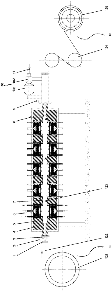
[0058] A gas-fired catalytic flameless near-infrared heating annealing furnace (see figure 1 ), the annealing furnace is used for bright annealing of stainless steel strips that need to ensure the atmosphere in the furnace. It includes a furnace shell 4, a furnace lining 7, a heating system, a cooling system 10, and a conveying system 12. The furnace shell is a high-temperature section, and the cooling system is a cooling part;

[0059] The cooling system 10 is installed at the rear end of the furnace shell 4. The cooling system 10 includes a heat exchanger 101 and a forced cooling fan 102. The rear end of the cooling system 10 is provided with a protective gas outlet 11;

[0060] The conveying system 12 includes an uncoiler 1201, stainless steel belt rollers 1203, S rollers 1204, and a coiler 1205 in the furnace. One end of the stainless steel belt 1202 is wound on the uncoiler 1201, and the other end passes through the furnace shell 4 and cooled in turn. System 10 , S roll ...

Embodiment 2

[0071]A gas catalytic flameless near-infrared heating annealing furnace, the annealing furnace is used for the annealing of stainless steel strips that do not need to ensure the atmosphere in the furnace. The basic structure of the annealing furnace is the same as that of the first embodiment. The rear end of 10 is not provided with a protective gas outlet 11; the front end of the furnace shell 4 is not provided with an inlet sealing device 1, a front protective gas release port 2, and a protective gas inlet 3 in the furnace chamber, and the rear end of the furnace shell 4 is not provided with a rear protective gas release. mouth 9.

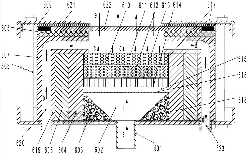
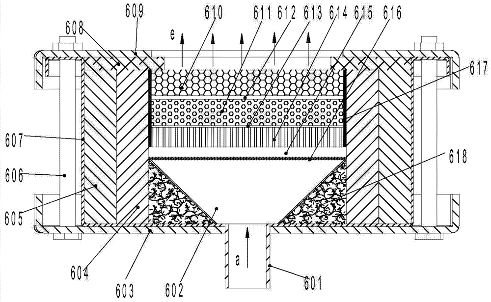
[0072] (2) The gas catalytic flameless near-infrared heating porous medium burner 6 is a gas catalytic flameless near-infrared direct heating porous medium burner (see image 3 ), which includes a burner body 607, an insulating layer 605, and a refractory brick layer 604. The refractory brick layer 604 is located in the burner body 607, and the i...


PUM

PropertyMeasurementUnit
thicknessaaaaaaaaaa
thicknessaaaaaaaaaa
thicknessaaaaaaaaaa

Abstract

A gas-fired catalytic flameless near-infrared heating annealing furnace, which relates to an annealing furnace, including a furnace shell, a furnace lining, a heating system, a cooling system, and a conveying system. A refractory material layer is arranged between the furnace shell and the furnace lining, and the heating system is embedded in the refractory material In the layer, it is a gas-fired catalytic flameless near-infrared heating porous media burner, which includes a burner body, an insulation layer, and a refractory brick layer. The refractory brick layer is equipped with a premixed gas diffusion chamber, a perforated plate, and a premixed gas pressure equalizer. The bottom of the premixed gas diffusion chamber is connected to the premixed gas supply pipe, and insulation cotton is arranged between the periphery of the premixed gas diffusion chamber and the refractory brick layer; the upper and lower parts of the burner body The lower end surfaces are connected together through upper and lower pressing plates and connecting pieces. The invention has high thermal efficiency, complete combustion, and low pollutant emission, and is applicable to the annealing process that needs to ensure the atmosphere in the furnace. It has the characteristics of high furnace temperature, low energy consumption, high output, and low maintenance cost, and is easy to popularize and use.

Description

technical field [0001] The invention relates to an annealing furnace, in particular to a gas-catalyzed flameless near-infrared heating annealing furnace. Background technique [0002] In machining, the workpiece is usually annealed. For example, after cold rolling, the stainless steel strip will produce work hardening. For this reason, it must be annealed so that the mechanical properties of the steel strip can meet the requirements of users. At present, the annealing furnaces on the market generally use direct-fired annealing furnaces. The heating system of such annealing furnaces has problems such as incomplete combustion, low thermal efficiency, poor combustion stability, and high emissions of combustion pollutants. [0003] In addition, the annealing furnaces that need to ensure the atmosphere in the furnace, such as the bright annealing furnace for stainless steel strips, are mainly electric heating muffle annealing furnaces. The so-called muffle refers to the annealing...

Claims


Application Information

Patent Timeline
Patent Type & Authority Patents(China)
IPC IPC(8): C21D9/00C21D1/26
Inventor 周海波
Owner 北京秦冶众智科技有限公司
Why Eureka
Try Eureka