Eureka AIR delivers breakthrough ideas for toughest innovation challenges, trusted by R&D personnel around the world.

High altitude gas detection system and detection method

A gas detection system and gas technology, used in control/regulation systems, analysis of gas mixtures, measurement devices, etc., can solve the problems of low response speed, difficult to reach, limited monitoring range, etc., and achieve the effect of improving detection accuracy

Pending Publication Date: 2017-11-24
SHENZHEN SOARABILITY TECH CO LTD +1
View PDF5 Cites 2 Cited by
  • Summary
  • Abstract
  • Description
  • Claims
  • Application Information

AI Technical Summary

Problems solved by technology

[0004] Technical defect 1: it is difficult to reach under complex terrain conditions;
[0005] Technical defect two: the problem of low response speed and limited monitoring range; and
[0006] Technical defect three: the problem of being unable to dynamically track and detect surrounding ambient gas parameters in real time
Although the above solution solves the technical problem of actively tracking and detecting the surrounding ambient gas parameters, however, when the rotor of the UAV system is working, it will discharge the surrounding ambient gas, and the gas will rise or fall through the discharge of the gas. In this process, the rotor of the UAV will cause eddy currents to the surrounding environment, so the above technical solution still has the following technical defects: the rotor changes the distribution of gas properties in the detection environment, resulting in inaccurate detection results

Method used


Image

  • High altitude gas detection system and detection method
  • High altitude gas detection system and detection method
  • High altitude gas detection system and detection method

Examples


Embodiment 1

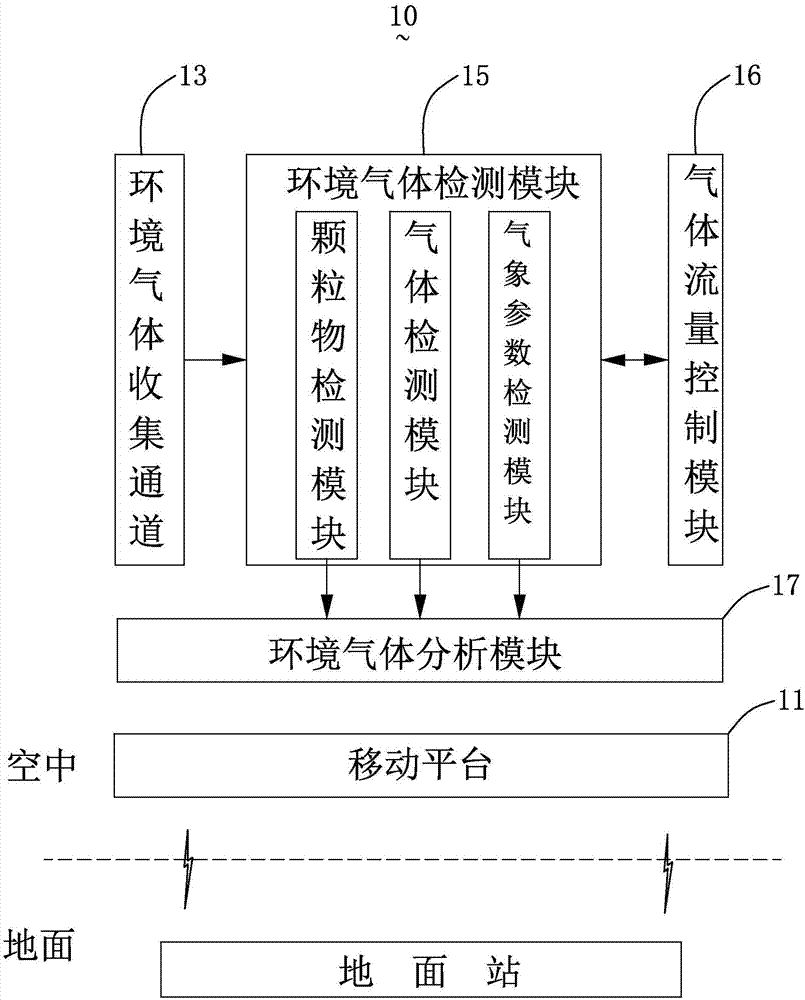
[0047] see Figure 6 , is one of the embodiments of the control method of the gas flow control module 16, the gas flow control module 16 includes a gas flow detector and an exhaust fan, and its control method includes the following steps:

[0048] Step S11, the mobile platform 11 hovers, and the ambient gas collection channel 13 contains the current ambient gas sample;

[0049] Step S12, the ambient gas detection module 15 correspondingly detects the gas parameters in the current ambient gas collection channel 13;

[0050] Step S13, the gas flow detector detects the gas flow at the gas outlet of the ambient gas collection channel 13;

[0051] Step S14, providing a driving signal according to the detection result of the gas flow detector to drive the gas flow control module 16 to continue to work according to the set power, so that the gas in the ambient gas collection channel 13 is renewed;

[0052] Step S15, when it is detected that the gas in the ambient gas collection cha...

Embodiment 2

[0056] see Figure 7 , is another embodiment of the control method of the gas flow control module 16, the gas flow control module 16 includes a flow detector and an exhaust fan, and the control method includes the following steps:

[0057] Step S21, providing a control signal to drive the mobile platform 11 to move in the ambient space to be detected, the ambient gas collection channel 13 collects gas samples to be detected, and the ambient gas detection module 15 performs periodic detection of the gas samples to be detected;

[0058] Step S22, providing a control signal to control the gas flow control module 16 to be in the first working state;

[0059] Step S23, the gas flow detector detects the gas flow in the ambient gas collection channel 13, so as to calculate the actual gas renewal rate of the ambient gas collection channel 13 within a period of time. The target gas update rate of the ambient gas collection channel 13 is calculated according to the sampling interval of...


PUM


Abstract

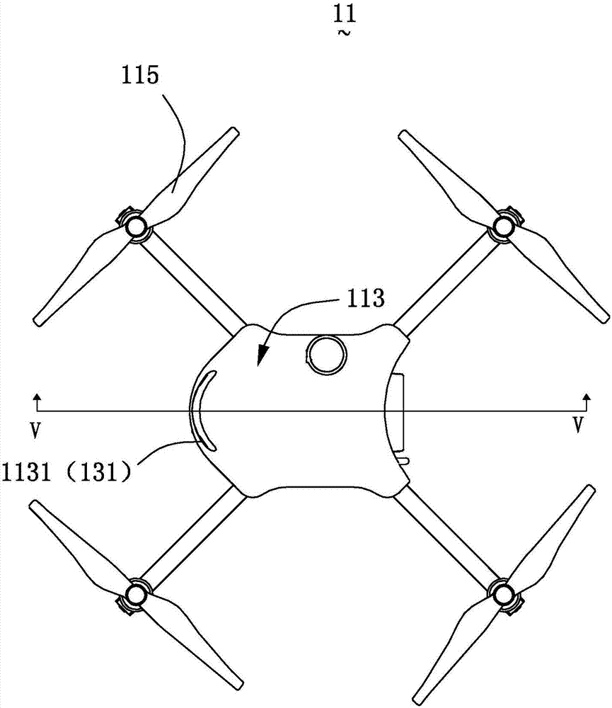
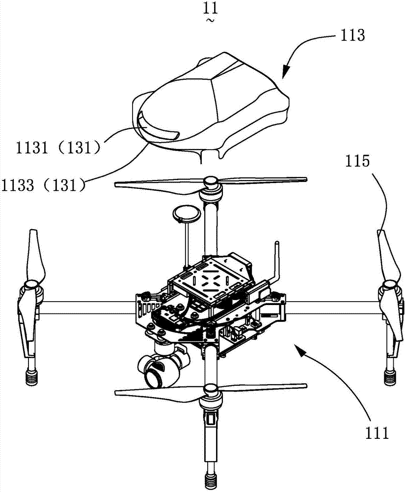
The invention discloses a high altitude gas detection system and a detection method. The detection system comprises a mobile platform, an environmental gas collecting channel, multiple gas sensors and a gas flow controller, wherein the mobile platform comprises a cover body; the environmental gas collecting channel comprises a gas inlet, a containing cavity and a gas outlet which are sequentially arranged in a cut-through way; and the gas inlet and the gas outlet are respectively formed in the opposite ends of the cover body II, the containing cavity is enclosed by the cover body and cuts through the gas inlet and the gas outlet, the gas sensors are contained in the containing cavity of the environmental gas collecting channel, and the gas flow controller controls flow rate of the gas collected in the environmental gas collecting channel and guarantees that gas in the environmental gas collecting channel is renewed timely. The high altitude gas detection system and method precisely detect gas parameter distribution of a surrounding environment in real time, and the sensors are avoided from being interfered by an external environment, so that detection precision is improved, and life is prolonged.

Description

technical field [0001] The invention relates to the technical field of gas detection, in particular to an ambient gas detection system and a detection method using a mobile platform of an unmanned aerial vehicle. Background technique [0002] UAV is unmanned aerial vehicle (UnmannedAerialVehicle) referred to as UAV. It has a history of more than 80 years since its birth in the early 20th century. Especially driven by the rapid development of electronics and aviation technology, the development of drones has attracted the attention of various countries. [0003] In the prior art, there are the following technical defects in the environmental monitoring system and its testing methods mainly composed of environmental testing vehicles, environmental testing boats and portable environmental testing equipment: [0004] Technical defect 1: it is difficult to reach under complex terrain conditions; [0005] Technical defect two: the problem of low response speed and limited monit...

Claims


Application Information

Patent Timeline
IPC IPC(8): G01N1/22G05D7/06G01N15/06G01N33/00G01D21/02
CPCG05D7/0623G01D21/02G01N1/2273G01N15/06G01N33/0004G01N2001/2279
Inventor 蒋抒彤曽建棠李琪
Owner SHENZHEN SOARABILITY TECH CO LTD
Why Eureka
Eureka Blog
Learn More