a biochip
A biochip and chip technology, applied in the direction of biomaterial analysis, instruments, measuring devices, etc., can solve the problems of many detection steps and long detection time, and achieve the effects of convenient use, low production cost and simple structure
- Summary
- Abstract
- Description
- Claims
- Application Information
AI Technical Summary
Problems solved by technology
Method used
Image

Examples
Embodiment 1
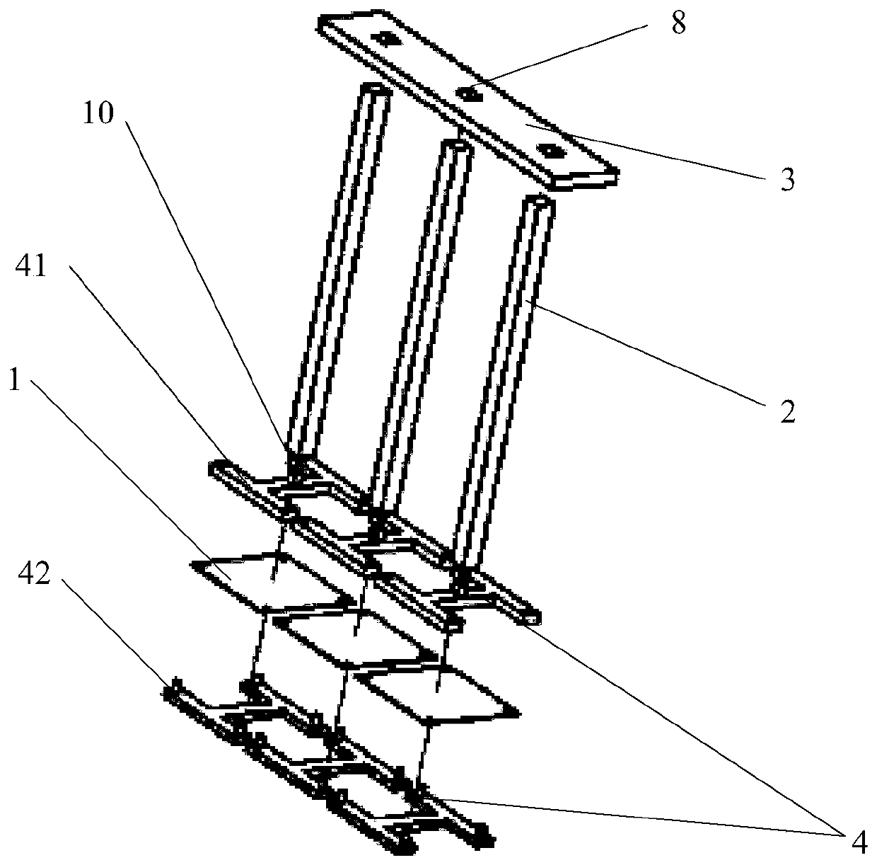
[0037] figure 1 A biochip 10 of one embodiment of the present invention is schematically shown. like figure 1 As shown, the biochip 10 of this embodiment includes a base 3 . In this embodiment, the base 3 is in the shape of an elongated plate with several holes 8 opened therein. The holes 8 are preferably arranged in an array. The biochip 10 also includes several chip handles 2 . In this embodiment, the chip handle 2 is an elongated cuboid, the number of which preferably corresponds to the number of the holes 8 one-to-one. Each chip handle 2 can be inserted into a corresponding hole 8 and held securely. It is easy to understand that various methods can be used to fix the chip handle 2 in the base 3 , such as snap-fitting, gluing, and the like. In an embodiment not shown, the chip handle 2 is detachably fixed to the base 3 .
[0038]According to the present invention, the biochip 10 further includes a chip reaction interface 1 for labeling the detection probe. The chip ...
example 1
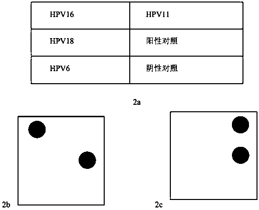
[0046] In this example, using figure 1 The biochip shown is used for identification of human papillomavirus genotyping, specifically for detecting common types of HPV nucleic acids (HPV16, HPV18, HPV6, HPV11).
[0047] HPV16 and HPV18 are the most common high-risk human papillomaviruses, which cause cervical cancer in women; HPV6 and HPV11 are the most common low-risk human papillomaviruses, which cause condyloma acuminatum. There are already vaccines against these four types of HPV.
[0048] The following describes the use of figure 1 The biochips are shown to carry out the various steps of the method for human papillomavirus identification.
[0049] Step 1: Fabrication of the chip reaction interface with the HPV genotyping probe immobilized
[0050] Design and synthesis of each HPV probe:
[0051] HPV16 probe sequence: TTTTTTTTTCTGAAGTAGATATGGCAGC
[0052] HPV18 probe sequence: TTTTTTTTTTTTATTGCCCAGGTACAGGA
[0053] HPV6 probe sequence: TTTTTTTTTGGAAGATGTAGTTACGGA
[...
Embodiment 2
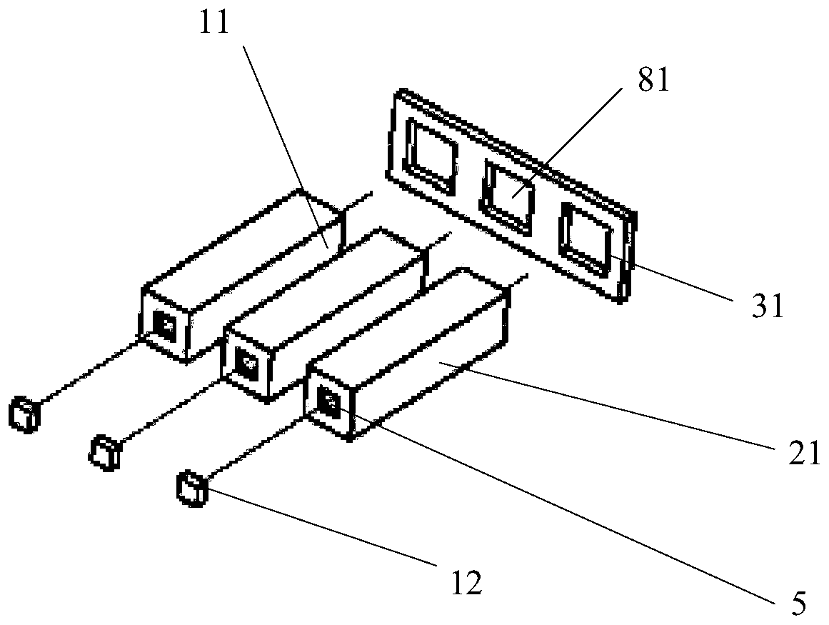
[0085] image 3 A biochip 11 of an embodiment of the present invention is schematically shown. like image 3 As shown, the biochip 11 of this embodiment includes a base 31 . In this embodiment, the base 31 is plate-shaped, and several holes 81 are opened therein. The holes 81 are preferably arranged in an array. The biochip 11 also includes several chip handles 21 . In this embodiment, the chip handle 21 is an elongated cuboid, the number of which preferably corresponds to the number of the holes 81 one-to-one. Each chip handle 21 can be inserted into a corresponding hole 81 and held securely. It is easy to understand that the chip handle 21 can be fixed in the base 31 in various ways, such as snap-fit, glue and the like. In a not-shown embodiment, the chip handle 21 is detachably secured to the base 31 .
[0086] According to the present invention, the biochip 11 further includes a chip reaction interface 12 for labeling the detection probe. The chip reaction interfac...
PUM
| Property | Measurement | Unit |
|---|---|---|
| diameter | aaaaa | aaaaa |
Abstract
Description
Claims
Application Information
 - R&D
- Intellectual Property
- Life Sciences
- Materials
- Tech Scout
- Unparalleled Data Quality
- Higher Quality Content
- 60% Fewer Hallucinations
Browse by: Latest US Patents, China's latest patents, Technical Efficacy Thesaurus, Application Domain, Technology Topic, Popular Technical Reports.
© 2025 PatSnap. All rights reserved.Legal|Privacy policy|Modern Slavery Act Transparency Statement|Sitemap|About US| Contact US: help@patsnap.com