
Contactless perception positioning method

A one-to-one, phase-difference technology, applied in the field of perception and positioning, can solve problems such as dependence on fingerprints, perception blind spots, and difficulty in guaranteeing real-time performance of two-dimensional spatial spectrum search algorithms, and achieve low-cost effects

Active Publication Date: 2017-11-24
PEKING UNIV
View PDF5 Cites 7 Cited by
  • Summary
  • Abstract
  • Description
  • Claims
  • Application Information

AI Technical Summary

Problems solved by technology

LiFS uses 11 devices (4 APs with 7 WiFi receivers) to achieve 70m 2 The median positioning error is 1.1m in the environment, but its location mapping still depends on fingerprints, and the NLoS positioning accuracy is low; MaTrack uses the multi-antenna AoA technology to directly adopt the geometric mapping scheme. 2 The positioning median error of 0.6m has been achieved in the environment, but the difficulty is that, on the one hand, although the number of paths to be identified is reduced based on static path fusion, it also leads to perception blind spots near the fusion angle; on the other hand, based on two The three-dimensional space spectrum search algorithm brings the difficulty of guaranteeing real-time performance, and the cumulative error is still based on the limitation of AoA positioning

Method used


Image

  • Contactless perception positioning method
  • Contactless perception positioning method
  • Contactless perception positioning method

Examples


Embodiment Construction

[0033] The present invention will be further described through examples below in conjunction with the accompanying drawings. It will be understood by those skilled in the art that the specific description is not intended to limit the scope of the present invention in any way.

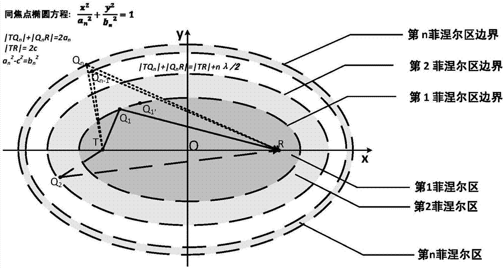
[0034] image 3 is a block diagram of a system for determining a Fresnel phase offset according to an embodiment of the present invention, wherein (a) is a sending device (which supports radio frequency signal transmission including Wi-Fi signals, such as Wi-Fi devices); (b) is a receiving device (which supports reception of radio frequency signals including Wi-Fi signals, such as a Wi-Fi device). It should be appreciated that in one embodiment the transmitting device (a) may not be part of the system for determining the Fresnel phase offset. For example, the transmitting device may be a system capable of transmitting radio frequency signals (such as Wi-Fi signal transmission) in the location where the...


PUM


Abstract

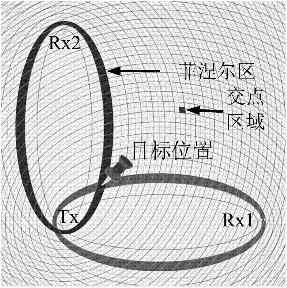
The present application discloses a method and system for determining a Fresnel phase shift in an environment and a computer readable storage medium. The method comprises a step of allowing a receiving device R to receive a radio frequency signal from a transmitting device T, wherein the radio frequency signal comprises two or more carriers, a step of constructing a K layer Fresnel area of the two or more carriers with the position of the transmitting device T and the position of the receiving device R as ellipse focuses, a step of laying a reflection target in the environment such that the reflection target moves in the environment, a step of determining a theoretical Fresnel phase difference between different carriers caused by the reflection target for at least one carrier pair combination in the at least two carriers, a step of determining an actual Fresnel phase difference between different carriers caused by the reflection target and the environment for the at least one carrier pair combination in the at least two carriers, and a step of comparing the actual Fresnel phase difference and the corresponding theoretical Fresnel phase difference, and determining the Fresnel phase shift of the at least one carrier pair combination in the environment. The invention also discloses a method of carrying out indoor positioning based on the method for determining a Fresnel phase shift in an environment.

Description

technical field [0001] The invention relates to perceptual positioning technology, in particular to an indoor non-contact perceptual positioning method based on commercial WiFi equipment. Background technique [0002] Contact-aware positioning refers to obtaining the position of the target when the positioning target does not carry any device and does not have any contact with the device. Compared with contact positioning methods, non-contact sensing positioning has the advantages of non-intrusive, convenient, and low-cost. Commercial WiFi devices are widely present in our daily life, so the realization of contactless sensing positioning technology on commercial WiFi devices has received extensive attention. [0003] Since Mousta Youssef first proposed the concept of Device-free passive localization (DfP) in 2007, WiFi-based non-contact indoor positioning has attracted the attention of many scholars, and a number of excellent works have emerged. Early work mainly uses WiFi...

Claims


Application Information

Patent Timeline
Patent Type & Authority Applications(China)
IPC IPC(8): G01S5/12G01S5/04G01S5/02G01R25/00
CPCG01R25/00G01S5/0252G01S5/04G01S5/12
Inventor 张大庆王皓牛凯
Owner PEKING UNIV
Learn More