
Wafer positioning device and method

A positioning device and wafer technology, which is applied in electrical components, semiconductor/solid-state device manufacturing, circuits, etc., can solve problems such as wafer damage, and achieve the effects of low cost, simple structure, and improved production quality.

Active Publication Date: 2017-11-24
ZING SEMICON CORP
View PDF5 Cites 5 Cited by
  • Summary
  • Abstract
  • Description
  • Claims
  • Application Information

AI Technical Summary

Problems solved by technology

[0006] In view of the above-mentioned shortcomings of the prior art, the object of the present invention is to provide a wafer positioning device and method for solving the problem in the prior art that wafer damage is easily caused when the wafer positioning device is used for positioning

Method used


Image

  • Wafer positioning device and method
  • Wafer positioning device and method
  • Wafer positioning device and method

Examples


Embodiment Construction

[0045] Embodiments of the present invention are described below through specific examples, and those skilled in the art can easily understand other advantages and effects of the present invention from the content disclosed in this specification. The present invention can also be implemented or applied through other different specific implementation modes, and various modifications or changes can be made to the details in this specification based on different viewpoints and applications without departing from the spirit of the present invention. It should be noted that, in the case of no conflict, the following embodiments and features in the embodiments can be combined with each other.

[0046] It should be noted that the diagrams provided in the following embodiments are only schematically illustrating the basic ideas of the present invention, and only the components related to the present invention are shown in the diagrams rather than the number, shape and shape of the compo...


PUM


Abstract

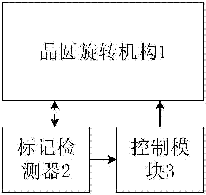
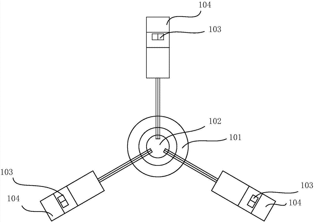
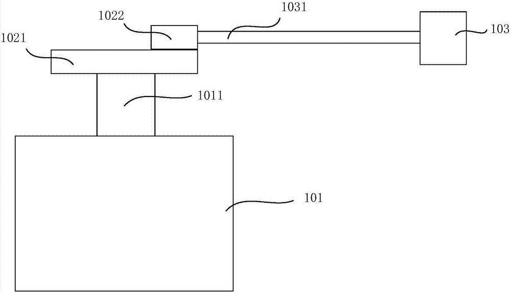
The invention provides a wafer positioning device and related method. The device comprises a wafer rotation mechanism, a mark detector and a control module, wherein the wafer rotation mechanism is provided with a rotation center and comprises driving wheels, the driving wheels are in contact with wafers and are used for driving the wafers to rotate around the rotation center, the mark detector is used for detecting positioning marks on the wafers and sending a detection result to the control module, and the control module is used for controlling the driving wheels according to the detection result of the mark detector so as to achieve wafer positioning. In the wafer positioning device, a traditional suction disc suction mode is substituted by employing the driving wheels to drive the wafers, the damage to the wafers can be prevented during positioning, multi-point detection and positioning can be achieved, multi-segment speed control is achieved, and the wafer positioning device is high in efficiency and accuracy, simple in structure and low in cost.

Description

technical field [0001] The invention relates to semiconductor manufacturing technology, in particular to a wafer positioning device and method. Background technique [0002] Wafer alignment control is one of the important links in the integrated circuit manufacturing process. During the manufacture of semiconductor wafers, markings for positioning are usually made on the wafer, such as notches provided on the edge of the wafer, common ones are V-notch, Flat and so on. [0003] These positioning marks can be detected by optical sensors or charge-coupled device (CCD) cameras and the like. An earlier wafer alignment device is disclosed in Japanese Patent Application No. 05045948 published on August 23, 1994. The positioning device disclosed in this patent utilizes a charge-coupled device (CCD) camera installed on the rotating table to detect the position of the semiconductor wafer on the rotating table and processes the image to detect the position of the center of gravity of...

Claims


Application Information

Patent Timeline
IPC IPC(8): H01L21/68
CPCH01L21/681
Inventor 赵旭良
Owner ZING SEMICON CORP
Learn More