
Water current vibrating multi-oscillator piezoelectric energy accumulator

A piezoelectric energy harvesting and vibration-induced technology, which is applied to piezoelectric effect/electrostrictive or magnetostrictive motors, electrical components, generators/motors, etc., can solve frequent replacement, safety hazards, waste of manpower and material resources and other issues, to achieve the effects of strong fluid adaptability, improved reliability, and strong power generation capacity

Active Publication Date: 2017-11-24
ZHEJIANG NORMAL UNIVERSITY
View PDF2 Cites 0 Cited by
  • Summary
  • Abstract
  • Description
  • Claims
  • Application Information

AI Technical Summary

Problems solved by technology

Manual meter reading is not only inefficient and wastes manpower and material resources, but more importantly, meter readers often go back and forth many times in vain because there is no one in the household, which seriously affects the accuracy and real-time performance of data statistics. Therefore, people began to develop tap water and gas Remote automatic meter reading system
Although the data processing and transmission technology of the existing meter reading system is very mature, there is no report on its practical promotion and application. Laying cables, such as laying temporary open wires, has potential safety hazards, and batteries need to be replaced frequently. The above two methods are difficult for users to accept. Therefore, it is imperative to develop a tap water meter that can achieve self-sufficiency in electric energy.

Method used


Image

  • Water current vibrating multi-oscillator piezoelectric energy accumulator
  • Water current vibrating multi-oscillator piezoelectric energy accumulator
  • Water current vibrating multi-oscillator piezoelectric energy accumulator

Examples


Embodiment Construction

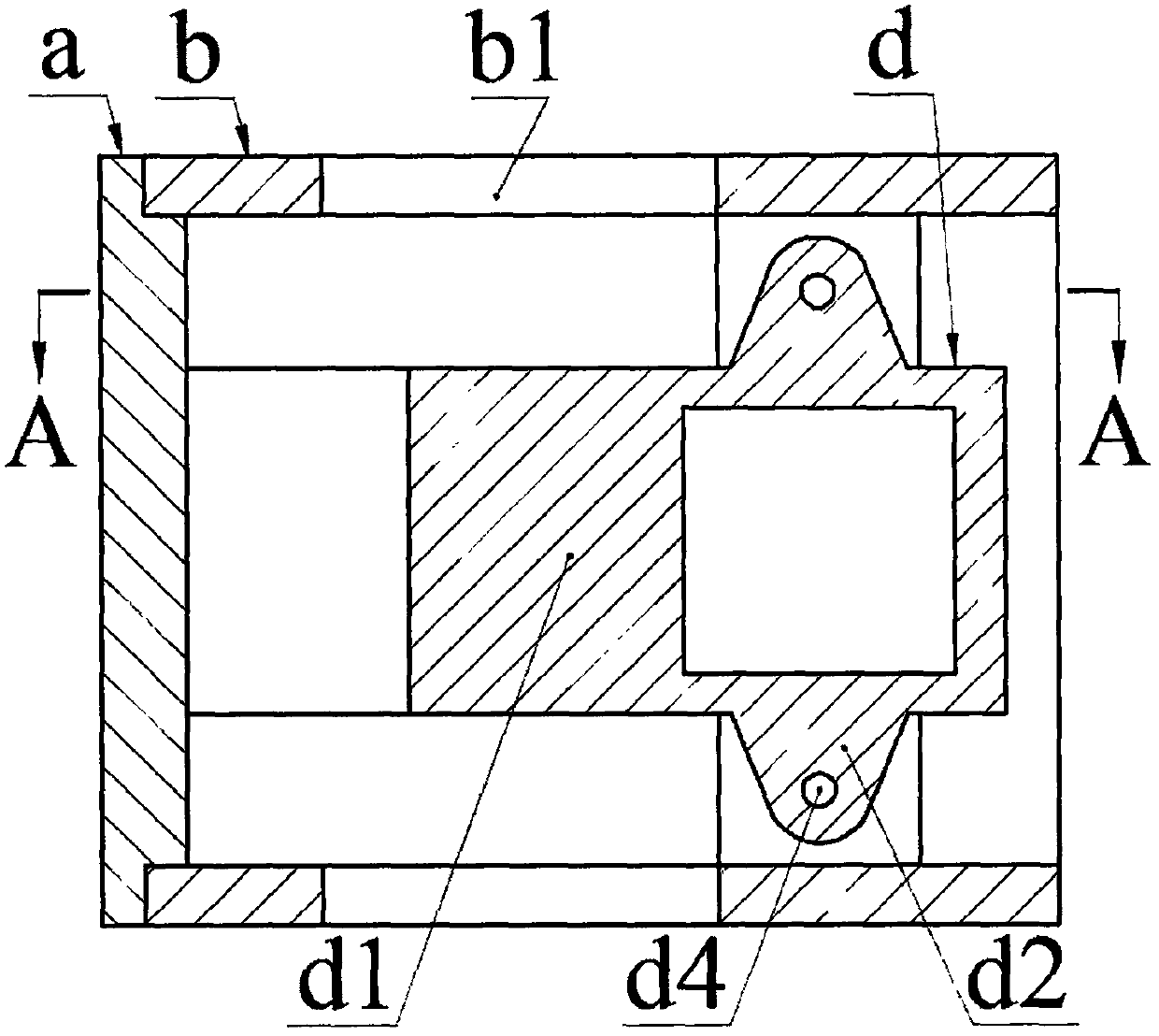
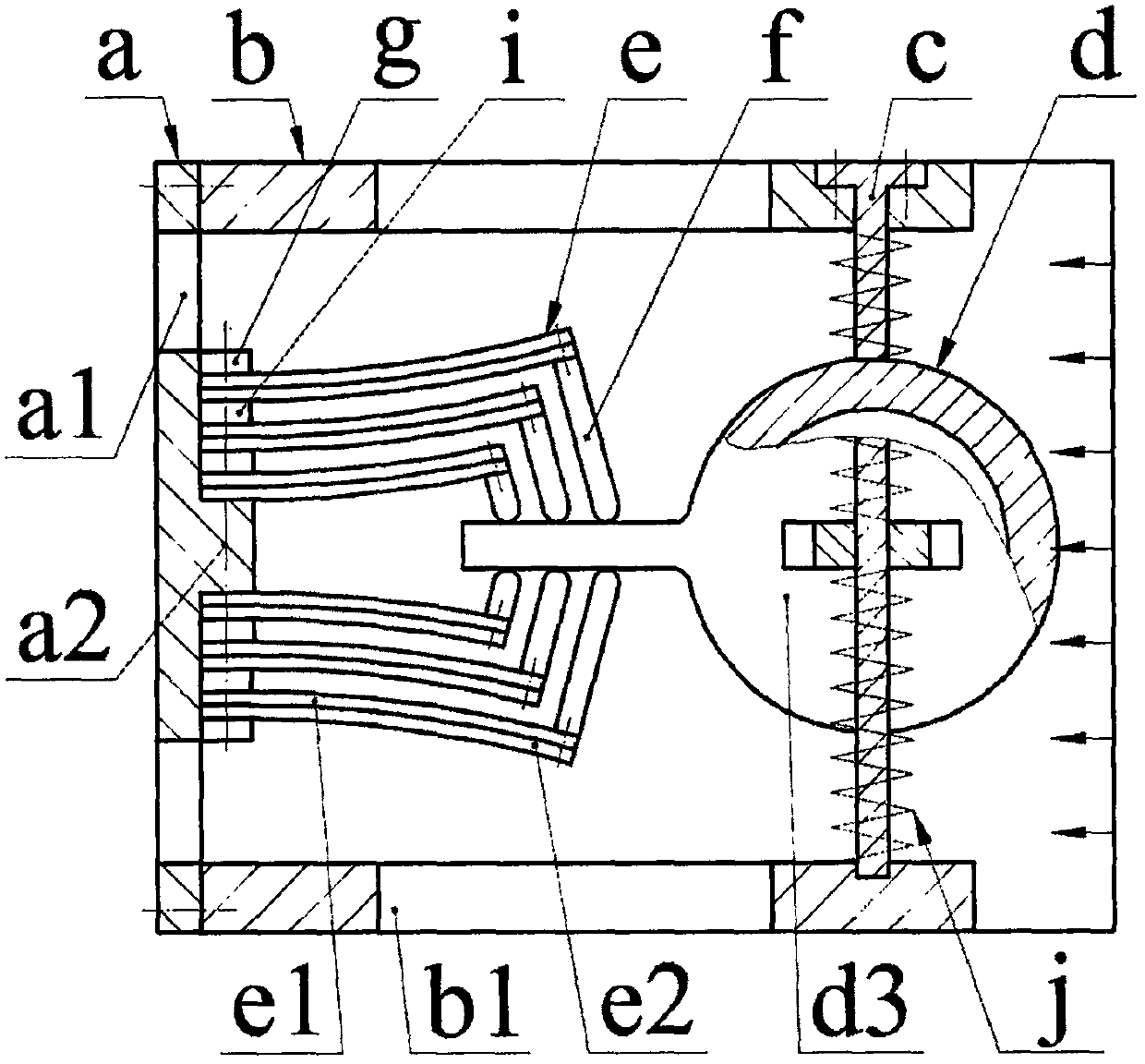
[0012] The housing b is provided with a flow hole b1, and the end is installed with a vertical plate a through screws. The vertical plate a is provided with a flow hole a1 and a boss a2, and the left and right sides of the boss a2 are installed by screws and pressure blocks g There are equal numbers of piezoelectric vibrators e; when the number of piezoelectric vibrators e installed on one side of the boss a2 is greater than 1, gaskets i are crimped between the fixed ends of two adjacent piezoelectric vibrators e, and the piezoelectric vibrators e is fixed by the pressure plate g through the screw and the gasket i; the piezoelectric vibrator e is formed by bonding the substrate e1 and the piezoelectric sheet e2, and the substrate e1 of the piezoelectric vibrator e on both sides of the boss a2 is installed close to it; the other part of the piezoelectric vibrator e One end is installed with a top block f via screws, and the top block f is placed on one side of the substrate e1 o...


PUM


Abstract

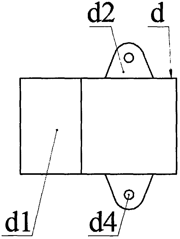
The invention relates to a water current vibrating multi-oscillator piezoelectric energy accumulator, and belongs to the fluid power generating field; a housing is provided with a flow passage hole; the end portion is provided with a vertical plate having a flow passage hole and a boss; the left side and right side of the boss are provided with piezoelectric oscillators of the same number; when the piezoelectric oscillator number arranged on one side of the boss is >1, a pad is pressed between fixed ends of two adjacent piezoelectric oscillators; the piezoelectric oscillator is formed by bonding a substrate and piezoelectric patches; the substrates of the piezoelectric oscillators on two sides of the boss are arranged nearby; the other end of the piezoelectric oscillator is provided with a push block; the push block is arranged on one side of the piezoelectric oscillator substrate, and the other end abuts against an exciter swing arm; the ear plate of the exciter with a hollow turbulent flow body is provided with a shaft hole; a guide pillar penetrates the shaft hole and is fixed on the housing side wall; the exciter is fixed on the top and bottom side walls through the ear plates, guide pillars, and springs; the piezoelectric oscillator is a flattened structure before installation and a bending structure after installation.

Description

technical field [0001] The invention belongs to the technical field of pipeline fluid power generation and pipeline monitoring, and in particular relates to a water flow-induced vibration multi-vibrator piezoelectric energy harvester. Background technique [0002] Tap water is an indispensable consumer product in the daily life of residents, and its consumption records and statistics are still mainly done manually. Manual meter reading is not only inefficient and wastes manpower and material resources, but more importantly, meter readers often go back and forth many times in vain because there is no one in the household, which seriously affects the accuracy and real-time performance of data statistics. Therefore, people began to develop tap water and gas Remote automatic meter reading system. Although the data processing and transmission technology of the existing meter reading system is very mature, there is no report on its practical promotion and application. Laying cab...

Claims


Application Information

Patent Timeline
Patent Type & Authority Applications(China)
IPC IPC(8): H02N2/18
CPCH02N2/185H02N2/186
Inventor 郑佳佳费翔程光明
Owner ZHEJIANG NORMAL UNIVERSITY
Learn More