Solar energy outdoor high-altitude interception apparatus with power storage function
An interception device and solar energy technology, applied in the field of solar energy, can solve the problems of easy to cause danger, danger to children, etc., and achieve the effects of being easy to slip, easy to use, and easy to make full use of
- Summary
- Abstract
- Description
- Claims
- Application Information
AI Technical Summary
Problems solved by technology
Method used
Image

Examples
Embodiment Construction
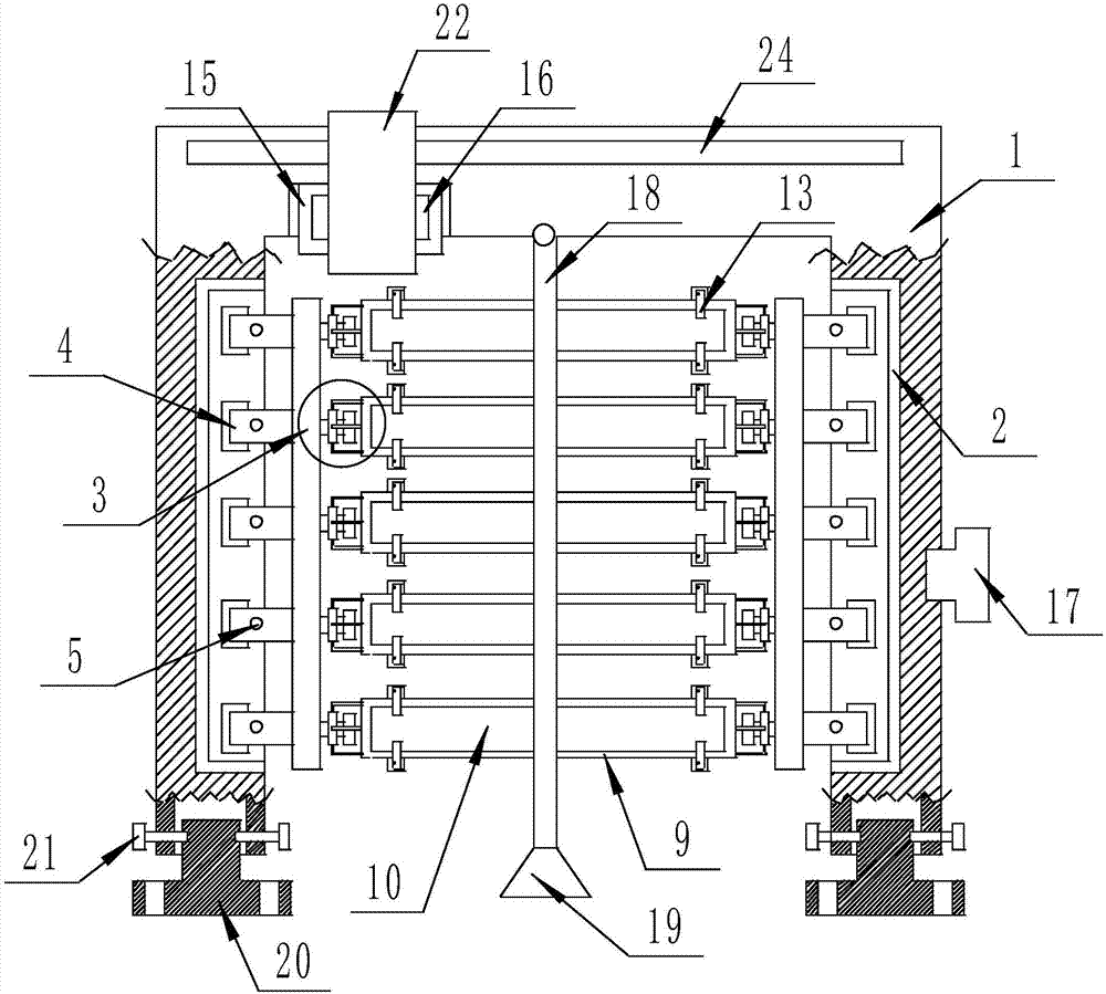
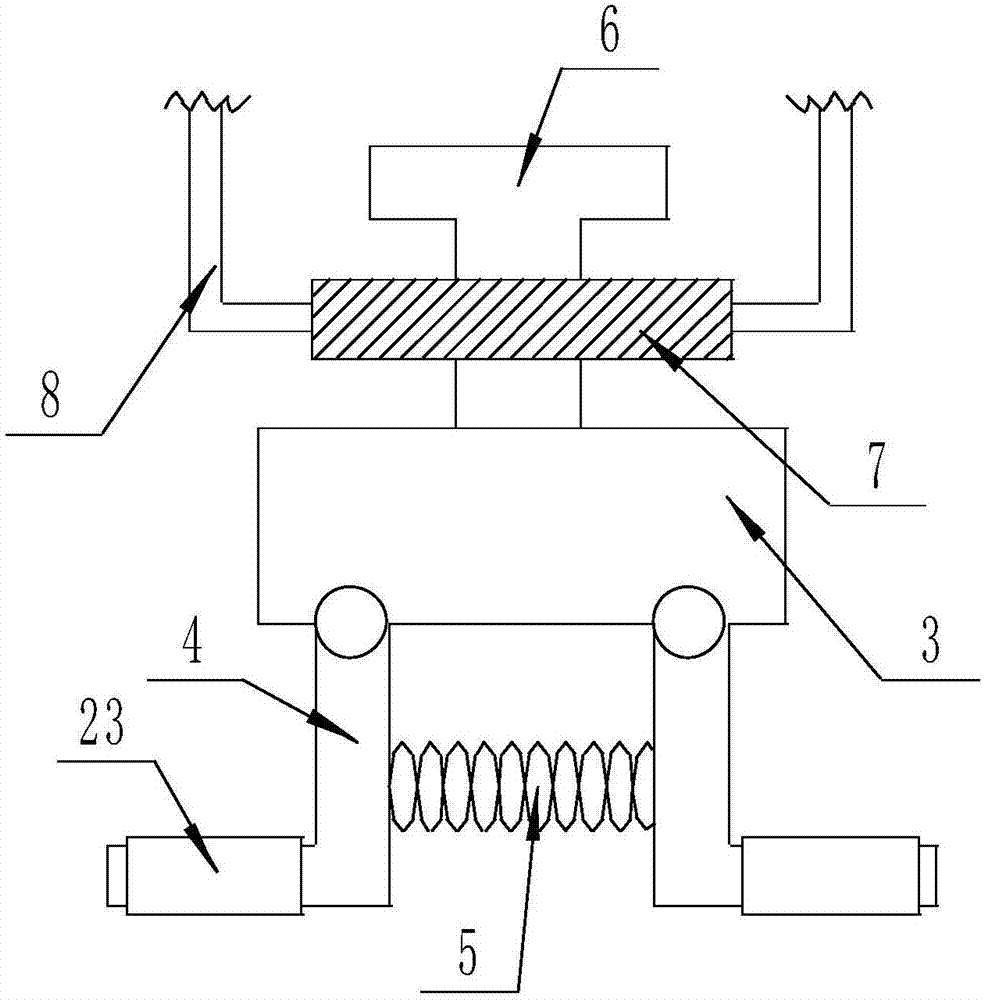
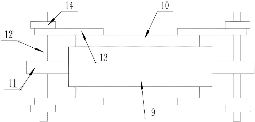
[0022] The present invention is specifically described below in conjunction with accompanying drawing, as Figure 1-5 As shown, a solar outdoor high-altitude interception device with power storage function includes an N-shaped support frame 1, the lower surface of the N-shaped support frame 1 is provided with a fixing mechanism, and the N-shaped support frame 1 is equipped with a power storage device. mechanism, the inside of the N-shaped support frame 1 is a hollow structure, and the storage mechanism consists of a group of vertical bar-shaped openings processed on the opposite side surfaces of the N-shaped support frame 1, embedded in each vertical bar-shaped The strip-shaped support shell 2 in the opening, the plurality of sets of No. 1 strip-shaped openings processed on two opposite side surfaces in each strip-shaped support shell 2, the strip-shaped support plate 3 arranged in each vertical strip-shaped opening, The hinges are connected on the side surface of each strip-s...
PUM
 Abstract
Description
Claims
Application Information