Dual-lens camera shooting machine
A camera and dual-lens technology, applied in the field of dual-lens cameras, to achieve the effect of light weight, flexible and efficient monitoring, and small size of equipment
- Summary
- Abstract
- Description
- Claims
- Application Information
AI Technical Summary
Problems solved by technology
Method used
Image
Examples
Embodiment 1
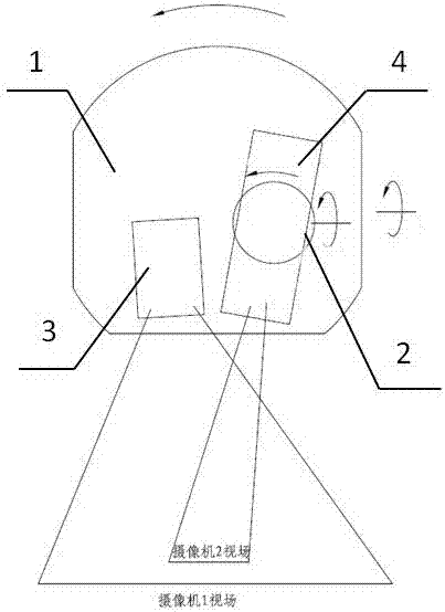
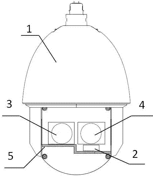
[0030] Example 1, such as figure 1 with figure 2 Shown: a dual-lens camera, the hardware implementation method is a dome camera structure, including the first bearing part 1 and the second bearing part 2. Can rotate horizontally and vertically. Wherein, a fixed plate 5 is installed on the bearing assembly of the dome camera, and the wide-angle lens 3 is fixedly installed on the fixed plate 5, and the angle of field of view of itself can be adjusted with the rotation of the bearing part-1. Also be provided with bearing part 2 2 on the fixed plate 5, the carrier part 2 2 can specifically be a miniature pan-tilt, and the telephoto lens 4 is installed on the miniature pan-tilt, so that when the whole dome bearing assembly rotates, the telephoto lens 4 can Turn individually to adjust the field of view angle of itself.
[0031] The camera with this structure can output a wide-angle field of view monitoring picture, and can also output a telephoto field of view monitoring picture...
Embodiment 2
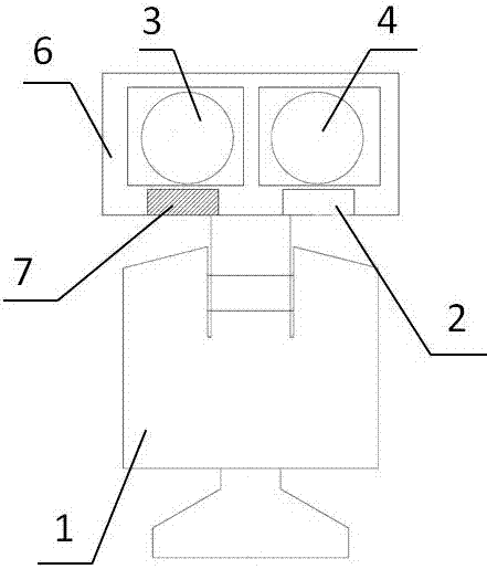
[0032] Example 2, such as image 3 As shown, the difference from Embodiment 1 is that the carrier part 1 is the main platform, and the carrier part 2 is a secondary platform and a miniature platform. The main cloud platform rotates vertically and horizontally, driving the camera mount 6 to rotate, and the camera mount 6 is provided with a fixed block, and the wide-angle lens 3 is fixedly connected to the camera mount 6 by the fixed block 7 . The telephoto lens 4 is installed on the camera mounting part 6 through the WeChat pan / tilt to achieve the same camera angle adjustment effect as in Embodiment 1.
Embodiment 3
[0033] Example 3, such as Figure 4 As shown, the hardware form of the whole device is similar to the gimbal gun. The mounting bracket 8 is installed on the mounting surface, and the carrier-1 can be a cloud platform, which rotates on the vertical and horizontal planes to drive the wide-angle lens 3 to rotate. The telephoto lens 4 is then directly installed on the wide-angle lens 3 through the carrier part 2, and also achieves the effect that the camera angles of the telephoto lens and the wide-angle lens are independently adjustable.
[0034] In these three embodiments, the telephoto lens and the wide-angle lens operate independently, which solves the technical problem that the current spherical camera cannot see the telephoto target after seeing the wide-angle, and loses the monitoring of the wide-angle field after seeing the telephoto.
[0035] On the other hand, the device has a simple structure and is good for real-time. It solves the problems of large volume, heavy weig...
PUM
 Abstract
Description
Claims
Application Information
 - R&D
- Intellectual Property
- Life Sciences
- Materials
- Tech Scout
- Unparalleled Data Quality
- Higher Quality Content
- 60% Fewer Hallucinations
Browse by: Latest US Patents, China's latest patents, Technical Efficacy Thesaurus, Application Domain, Technology Topic, Popular Technical Reports.
© 2025 PatSnap. All rights reserved.Legal|Privacy policy|Modern Slavery Act Transparency Statement|Sitemap|About US| Contact US: help@patsnap.com


