Cabinet system

A cabinet and backplane technology, used in cooling/ventilation/heating renovation, electrical components, electrical equipment structural components, etc., can solve the problems of limited heat dissipation openings, low heat dissipation efficiency, etc. Solve the effect of low heat dissipation efficiency

Active Publication Date: 2017-11-24
ZTE CORP
View PDF3 Cites 7 Cited by
  • Summary
  • Abstract
  • Description
  • Claims
  • Application Information

AI Technical Summary

Problems solved by technology

[0006] The embodiment of the present invention provides a cabinet system to at least solve the problem in the related art that the heat dissipation openings of the cabinet system are limited by the electrical interconnection between functional modules, resulting in low heat dissipation efficiency

Method used


Image

  • Cabinet system
  • Cabinet system
  • Cabinet system

Examples


Embodiment 1

[0033] Figure 4a is a schematic front view of a cabinet system according to an embodiment of the present invention, Figure 4b is a top view of a cabinet system according to an embodiment of the present invention, such as Figure 4a and Figure 4b As shown, the cabinet system 1 includes: a backplane device 1-1 composed of 2N+1 sub-backplanes, a function board 1-2, and a fan 1-3;

[0034] Wherein, the sub-backplane includes: a first interconnection backplane 1-1-1 and a second interconnection backplane 1-1-2; every two first interconnection backplanes 1-1-1 are provided with a second interconnection Backplane 1-1-2;

[0035] The functional board 1-2 is horizontally arranged between the first interconnected backplane 1-1-1 and the second interconnected backplane 1-1-2, and is connected to the first interconnected backplane 1-1-1 and the second interconnected backplane respectively. Backplane 1-1-2 horizontal orthogonal connection;

[0036] The fans 1-3 are arranged between...

Embodiment 2

[0043] The cabinet system 1 involved in this embodiment also includes connectors 1-4, such as Figure 5a and Figure 5b as shown, Figure 5a~5b is a schematic structural diagram of a cabinet system including a connector according to an embodiment of the present invention;

[0044] Among them, the connector 1-4 includes: a first connector 1-4-1 arranged on the same side of the first interconnected backplane as the second interconnected backplane; a second connector arranged on both sides of the second interconnected backplane 1-4-2; the third connector 1-4-3 arranged on the function board and connected orthogonally to the first connector 1-4-1; arranged on the function board and connected to the second connector 1-4 - 2 fourth connectors 1-4-4 of orthogonal connection; the third connector 1-4-3 is in conduction with the fourth connector 1-4-4.

[0045] It should be noted that the third connector 1-4-3 and the fourth connector 1-4-4 involved in this embodiment can be disposed...

Embodiment 3

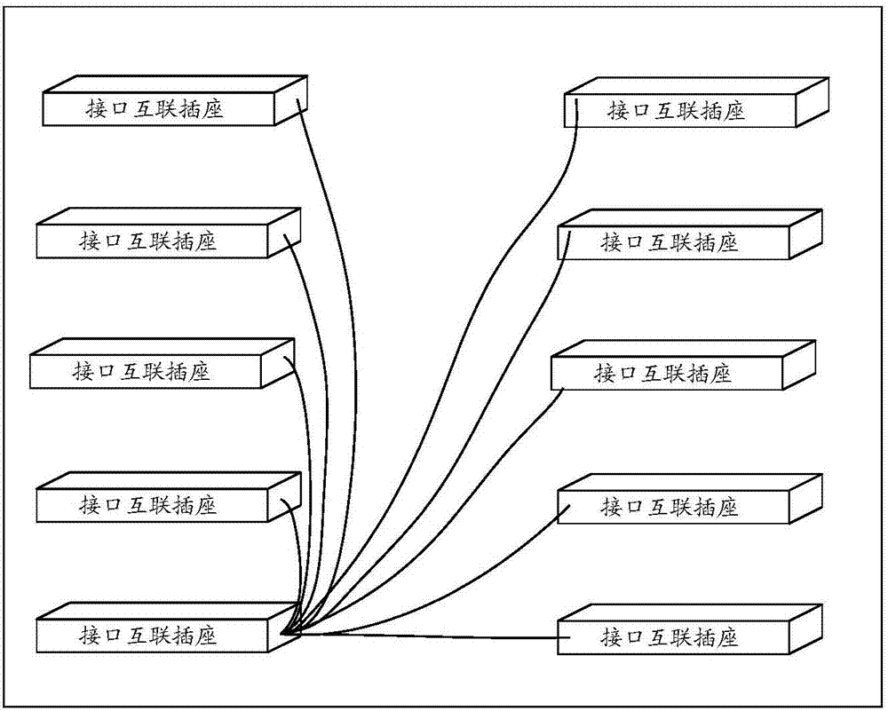
[0048] This embodiment is the implementation of the above-mentioned Embodiment 1 and Embodiment 2 in a specific application scenario. This embodiment uses a cabinet as an example to illustrate the present invention. The full Mesh positive interactive online cabinet system, such as Figure 6 as shown, Figure 6 It is a schematic structural diagram of a cabinet system including a backplane device according to an embodiment of the present invention Figure 1 ;

[0049] The cabinet system includes: a backplane device, wherein the backplane device includes three sub-backplanes: an upper and lower interconnected backplane 1 (corresponding to the first interconnected backplane in the above-mentioned embodiment), and an upper and lower interconnected backplane 2 (corresponding to the above-mentioned The first interconnection backplane in the embodiment), the horizontal interconnection backplane (corresponding to the second interconnection backplane in the above embodiment), and the ...


PUM


Abstract

The invention provides a cabinet system. The cabinet system comprises a back panel device, a functional plate and a fan, wherein the back panel device comprises (2N+1) sub back panels, each sub back panel comprises first interconnection back panels and a second interconnection back panel, the second interconnection back panel is arranged between each two first interconnection back panels at equal interval, the functional plate is horizontally arranged between the first interconnection back panels and the second interconnection back panel and is horizontally and orthogonally connected with the first interconnection back panels and the second interconnection back panels, the fan is arranged between the first interconnection back panels and the second interconnection back panel and on a plane perpendicular to a plane where the first interconnection back panels and the second interconnection back panel are located, and N is an integer more than or equal to 1. By the cabinet system, the problem of low heat dissipation efficiency caused by a heat dissipation opening hole, limited by electrical interconnection between functional modules, of a cabinet system in the relevant art is solved.

Description

technical field [0001] The present invention relates to the field of cabinets, in particular to a cabinet system. Background technique [0002] Among the equipment in the field of communication and electronics, the architecture based on server products is the development trend of large-capacity centralized processing cabinets in the future, and the heat dissipation method of the server architecture is to suck air through the tail fan, so that the wind enters from the front panel and is carried out by the wind. The heat of the functional modules flows out from the rear, that is, the front and rear air ducts dissipate heat. In addition, the cabinet realizes the centralized placement of each functional module, and the expansion of its processing capacity only needs to configure a corresponding number of functional modules. Therefore, there is a need for system interconnection between functional modules. At present, printed circuit boards (PCBs) are still used in the industry. ...

Claims


Application Information

Patent Timeline
Patent Type & Authority Applications(China)
IPC IPC(8): H05K7/20
CPCH05K7/20718H05K7/20
Inventor 龙细军杨雪舒新建余细红
Owner ZTE CORP
Why Eureka
Try Eureka