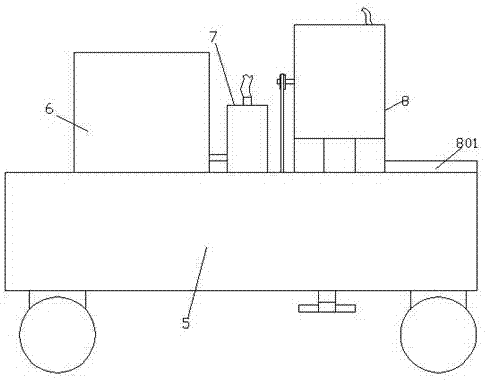
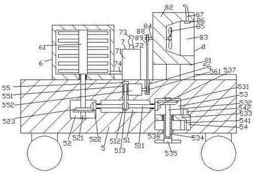
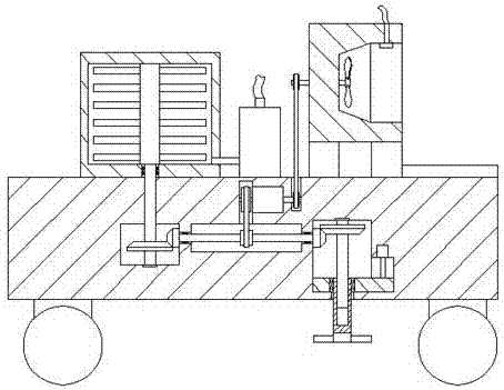
[0019] Such as Figure 1-Figure 4 As shown, a new energy vehicle for municipal gardens of the present invention includes a platform body 5, a cabinet 6 arranged on the top left side of the platform body 5, and an irrigation device 8 arranged on the top right side of the platform body 5. The top of the platform body 5 between the cabinet 6 and the irrigation device 8 is fixedly provided with a driving mechanism 7, and the cabinet 6 is provided with a mixing device 61, and the cabinet directly below the cabinet 6 The table body 5 is provided with a first chamber 52, and the first chamber 52 is provided with a mixing device for driving the mixing device 61 to rotate, and the table body on the right side of the first chamber 52 5 is provided with a second chamber 51, the platform 5 on the right side of the second chamber 51 is provided with a third chamber 53, and the top wall of the second chamber 51 is connected with a first side Slot 55, the second cavity 51 is provided with a second adapter shaft 511 extending left and right, and the left side extension of the second adapter shaft 511 passes through the first cavity 52 and the second The table body 5 between the chambers 51 is transferred, and the left end of the second transfer shaft 511 protrudes into the first chamber 52 and is fixedly provided with a matching connection with the mixing device The second cone runner 522, the right extension of the second adapter shaft 511 passes through the table body 5 between the third chamber 53 and the second chamber 51 and is transferred. The right end of the second adapter shaft 511 penetrates into the third cavity 53 and is fixedly provided with a third cone runner 537, and a first conversion wheel 551 is provided in the first square groove 55. The outer surface of the second adapter shaft 511 opposite to the bottom of the conversion wheel 551 is fixedly provided with a second conversion wheel 512, and a first conversion belt 513 is fitted and connected between the second conversion wheel 512 and the first conversion wheel 551 The right side of the first conversion wheel 551 is matedly connected with a first electric drive device 552. The outer surface of the first electric drive device 552 is arranged on the inner wall of the right side of the first square groove 55 and is fixedly connected. The platform 5 on the right side of an electric drive device 552 is provided with a second square slot 56 whose top passes through the top of the platform 5. The second square slot 56 is located between the drive mechanism 7 and the irrigation device. 8, the second square groove 56 is provided with a third conversion wheel 561 that is matched with the right end of the first electric drive device 552, and the third conversion wheel 561 is used to convert and cooperate with the irrigation device 8. Connected, the third chamber 53 is provided with a trimming fulfillment device for matingly connected with the third cone runner 537, and a water collecting box 801 is fixedly arranged on the top of the right side of the table body 5, the water collecting box The left part of 801 is fixedly connected with the outer wall of the irrigation device 8.
[0020] Wherein, the mixing device includes a first adapter shaft 521 arranged in the first chamber 52 and extending up and down. The top extension of the first adapter shaft 521 passes through the first chamber 52 The inner top wall and the bottom of the cabinet 6 are respectively connected with the inner top wall of the first chamber 52 and the bottom of the cabinet 6, and the top end of the first adapter shaft 521 is connected to the mixing device 61 In a fixed connection, the extended tip of the bottom of the first adapter shaft 521 is connected to the inner bottom wall of the first chamber 52, and the outer surface of the first adapter shaft 521 in the first chamber 52 is fixedly provided There is a first cone runner 523 that is matched with the second cone runner 522, so as to realize automatic control of water mixing and improve the uniformity of spraying.
[0021] Wherein, the driving mechanism 7 includes a power pump 71, a first connecting pipe 74 is provided between the left side of the power pump 71 and the right side of the cabinet 6, and a port 72 is provided on the top of the power pump 71, Thereby increasing the spraying speed of water and realizing automatic control of irrigation work, reducing the labor of workers.
[0022] Wherein, the irrigation device 8 includes a bottom frame 81 and an irrigation frame 82 fixed on the top of the bottom frame 81. The right side of the irrigation frame 82 is provided with an irrigation cavity 83, and the left side of the irrigation cavity 83 is provided on the inner wall. There is a paddle 85, the left side of the irrigation cavity 83 is connected with a third adapter shaft 84 extending left and right, and the left side of the third adapter shaft 84 extends to the outside of the left side of the irrigation frame 82, The third adapter shaft 84 outside the left side of the irrigation frame 82 is fixedly provided with a fourth conversion wheel 88 disposed opposite to the third conversion wheel 561, and the fourth conversion wheel 88 is connected to the third conversion wheel 561. A second conversion belt 89 is matched and connected between the wheels 561. The right side of the third adapter shaft 84 extends into the irrigation cavity 83 and is fixedly connected with the paddle 85. The inner top of the irrigation cavity 83 An irrigation head 86 is fixed on the wall. The top of the irrigation head 86 is fixed with a second connecting pipe 87 passing through the top of the irrigation frame 82. A second connecting pipe 87 is provided between the top of the second connecting pipe 87 and the port 72. The three-way pipe 73 is used to improve the water spraying effect and spraying range.
[0023] Wherein, the trim fulfillment device includes a clamping shaft 532 arranged in the third chamber 53 and extending up and down, and a guide groove 54 arranged in the inner wall of the right side of the third chamber 53. The inner bottom wall of the third chamber 53 is provided with a perforation 536 passing through the bottom of the platform body 5. The guide groove 54 is provided with a screw 541 extending up and down. The top of the screw 541 extends from the tip and the second electric drive The device 542 is matedly connected, the outer surface of the second electric drive device 542 is arranged on the top of the guide groove 54 and is fixedly connected, the bottom of the screw 541 extends and the tip is connected to the inner bottom wall of the guide groove 54, so A guide plate 533 extending to the left is slidably connected to the guide groove 54. The guide plate 533 in the guide groove 54 is connected to the screw 541 in a spiral pattern. The guide plate The left side extension section of 533 protrudes into the third cavity 53 and is slidably connected. The guide plate 533 in the third cavity 53 is transferred with a clamping sleeve 534 extending downwardly. The bottom extension of the clamping sleeve 534 passes through the perforation 536 and then reaches outside the bottom of the table body 5, and the tip is detachably fixedly connected with scissors 535. The bottom of the clamping shaft 532 extends and the tip penetrates into the clamping sleeve. 534 and slidably connected, and a mating fourth cone runner 531 is fixed on the clamping shaft 532 on the upper right side of the third cone runner 537, which reduces procurement costs and enhances the practicability and function of the device At the same time, the height adjustment of the scissors 535 can be realized.
[0024] In the initial state, the guide plate 533 is at the top position in the guide groove 54. At this time, the guide plate 533 drives the upper section of the clamping sleeve 534 into the third chamber 53 to the maximum extent. The socket 534 drives the scissors 535 away from the ground as far as possible. At this time, the extended section of the bottom of the clamping shaft 532 is pushed into the clamping socket 534 to the maximum.
[0025] When spraying and trimming are needed, the screw 541 is driven to rotate by the second electric drive device 542, and the screw 541 drives the guide plate 533 to gradually slide along the bottom of the guide groove 54. At this time, the guide plate 533 drives the clamping sleeve 534 slides down, and at the same time, the clip sleeve 534 drives the scissors 535 to move down. At this time, the clip shaft 532 slides into the clip sleeve 534 until it is adjusted to the required height, and the second electric drive device 542 is controlled to stop Then, the first conversion wheel 551 at the left end and the third conversion wheel 561 at the right end are driven by the first electric drive device 552. At this time, the first conversion wheel 551 drives the second conversion wheel 512 and the second conversion wheel 512 through the first conversion belt 513. The adapter shaft 511 rotates, and the second adapter shaft 511 drives the second cone runner 522 and the third cone runner 537 on the left and right sides to rotate. At this time, the third cone runner 537 drives the fourth cone runner 531 and the clamping shaft 532 on the fourth cone runner 531 rotate, and the clamping shaft 532 drives the clamping sleeve 534 and the scissors 535 at the bottom of the clamping sleeve 534 to rotate to realize the trimming work. At the same time, the second cone runner 522 drives the first cone runner 523 and the first adapter shaft 521 on the first cone runner 523 to rotate, and then the first adapter shaft 521 drives the mixing device 61 in the cabinet 6 to achieve mixing. At the same time, The third conversion wheel 561 drives the fourth conversion wheel 88 and the third adapter shaft 84 on the fourth conversion wheel 88 to rotate through the second conversion belt 89, and the third adapter shaft 84 drives the paddle 85 to rotate. When spraying water, control the power pump 71 to work so that the water in the cabinet 6 flows into the power pump 71 through the first connecting pipe 74, and then pressurized by the power pump 71 to make the water pass through the port 72, the third connecting pipe 73 and the first connecting pipe 74. The second connecting pipe 87 flows into the irrigation head 86 in turn, and finally sprays out through the irrigation head 86. At this time, the water sprayed from the irrigation head 86 is blown by the paddle 85 to make the water spray out of the irrigation frame 82. When 533 is at the bottom of the guide groove 54 image 3 As shown, at this time, the clip sleeve 534 drives the scissors 535 to be close to the ground as much as possible. When cutting and trimming are not required, the scissors 535 can be detached from the bottom of the clip sleeve 534.
[0026] The beneficial effects of the present invention are:
[0027] 1. Pass through the platform between the third chamber and the second chamber through the right extension of the second adapter shaft and transfer it. The right end of the second adapter shaft penetrates into the third chamber and the first The three-cone runner, the first conversion wheel is arranged in the first square groove, the second conversion wheel is fixed on the outer surface of the second adapter shaft opposite to the bottom of the first conversion wheel, and the second conversion wheel and the first conversion wheel are matedly connected The first conversion belt, the right side of the first conversion wheel is matched with the first electric drive device, the outer surface of the first electric drive device is arranged on the inner wall of the right side of the first square groove and fixedly connected, and the first electric drive device is inside the platform on the right side A second square groove with the top passing through the top of the platform is provided. The second square groove is equipped with a third conversion wheel that is matched with the right end of the first electric drive device to realize the conversion and connection of mixing, irrigation and trimming, and improve work efficiency .
[0028] 2. The irrigation device includes an underframe and an irrigation frame fixed on the top of the underframe. The right side of the irrigation frame is equipped with an irrigation cavity, the left side of the irrigation cavity is equipped with paddles, and the left side of the irrigation cavity is connected to the third extending left and right. Adapter shaft. The left side of the third adapter shaft extends from the tip to the left side of the irrigation rack. The third adapter shaft on the left side of the irrigation rack is fixedly provided with a fourth conversion wheel opposite to the third conversion wheel. The fourth conversion wheel and the third conversion wheel are connected to the second conversion belt. The right side of the third conversion shaft extends into the irrigation cavity and is fixedly connected with the paddle. The top wall of the irrigation cavity is fixed with an irrigation head for irrigation. The top of the head is fixedly provided with a second connecting pipe passing through the top of the irrigation rack, and a third connecting pipe is arranged between the top of the second connecting pipe and the port, thereby improving the water spraying effect and the spraying range.
[0029] 3. The trimming fulfillment device includes a clamping shaft arranged in the third chamber and extending up and down, and a guide groove arranged in the inner wall of the right side of the third chamber, and the bottom wall of the third chamber is provided with the bottom of the platform. The guide groove is provided with a screw rod extending up and down. The top of the screw rod extends and connects to the second electric drive device. The outer surface of the second electric drive device is arranged at the top of the guide groove and is fixedly connected. The inner bottom wall of the guide groove is transferred, and the guide plate extending to the left is slid in the guide groove. The guide plate in the guide groove is connected with the spiral pattern of the screw, and the left extension of the guide plate penetrates The third cavity is slidable, and the guide plate in the third cavity is transferred to the downwardly extending clamping sleeve. The bottom extension of the clamping sleeve penetrates the perforation and reaches outside the bottom of the platform, and the tip is detachable and fixed The scissors are connected to reduce purchase costs, enhance the practicability and functionality of the device, and at the same time, realize the height adjustment of the scissors.
[0030] 4. The invention has simple structure and convenient operation, can realize automatic control of mixing and irrigation, increase the range of water spraying, realize automatic control of pruning, reduce purchase costs, and enhance the practicability and functionality of the device.
[0031] The above are only specific implementations of the present invention, but the protection scope of the present invention is not limited thereto. Any changes or replacements that are not thought of through creative work shall be covered by the protection scope of the present invention. Therefore, the protection scope of the present invention should be subject to the protection scope defined by the claims.