

Movable well logging sand washing device
A technology of moving base and sand bucket, which is applied to cleaning hollow objects, wet separation, water/sludge/sewage treatment, etc. The cost of cleaning sand, the effect of sand washing is good, and the effect of improving sand washing efficiency
- Summary
- Abstract
- Description
- Claims
- Application Information
AI Technical Summary
Problems solved by technology
Method used
Image

Examples
Embodiment 1
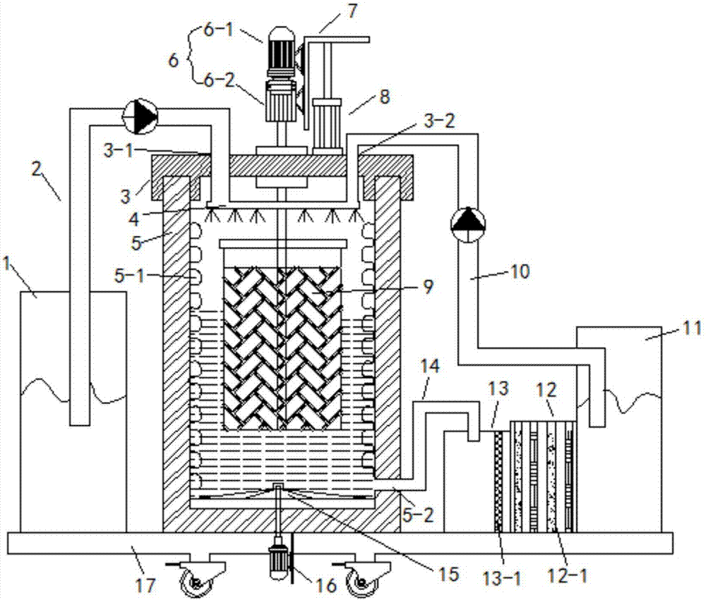
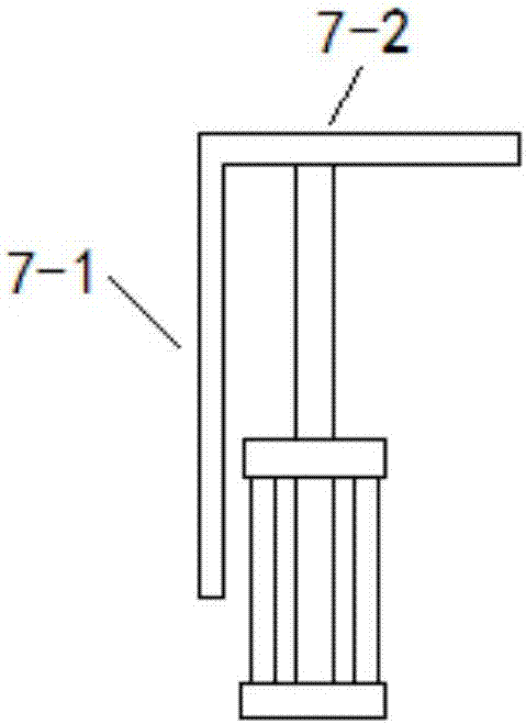
[0026] Such as Figure 1 to Figure 3 As shown, the present embodiment provides a movable mud logging sand washing device, comprising a mobile base 17, a sand cleaning tank 5 positioned on the mobile base 17 and a sand holding bucket 9 positioned in the sand cleaning tank 5, the sand cleaning The pool 5 is provided with a cover plate 3, and the cover plate 3 is dug with a water inlet, and the water inlet is connected with an annular water spray pipe 4 whose inner diameter is greater than the outer diameter of the sand holding bucket 9 in the sand cleaning tank 5. There is a water outlet 5-2 at the lower end of the pool wall, and the cover plate 3 is provided with a rotary drive assembly 6 and a lifting drive assembly 8 that drives the rotary drive assembly 6 to move up and down. The output end of the rotary drive assembly 6 extends through the cover plate 3 into the sand cleaning tank 5, and pass through the top of the sand tank 9 to be fixedly connected to the top and the bott...
Embodiment 2
[0029] This embodiment is further optimized on the basis of Embodiment 1, specifically:
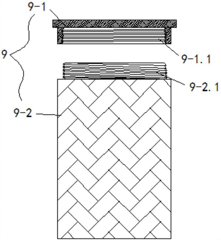
[0030]The sand holding bucket 9 includes a bucket cover 9-1 and a bucket body 9-2. The upper end of the bucket body 9-2 is open, and the opening is provided with an internal thread 9-2.1, and the inner wall of the bucket cover 9-1 is provided with a The external thread 9-1.1 matched with thread 9-2.1 is convenient to disassemble and open the sand bucket. The mobile base 17 is provided with a clean water tank 1 and a return water tank 11. The water inlet includes a clean water port 3-1 and a return water port 3- 2. The clean water tank 1 is connected with the clean water port 3-1 through the clean water pipe 2, the return water tank 11 is connected with the return water port 3-2 through the return water pipe 10, the return water tank 11 is connected with a secondary filter pool, and the water outlet 5-1 Communicate with the secondary filter tank through the water outlet pipe 14, the second...
PUM
 Abstract
Description
Claims
Application Information