Punching die for collecting punched waste

A scrap and punching technology, applied in the direction of piercing tools, manufacturing tools, feeding devices, etc., can solve the problems that affect the normal operation of the production line, cannot be removed, time-consuming and labor-intensive, etc.

Inactive Publication Date: 2017-11-28
NINGBO ZHENHAI YONGDING FASTENER
View PDF11 Cites 12 Cited by
  • Summary
  • Abstract
  • Description
  • Claims
  • Application Information

AI Technical Summary

Problems solved by technology

However, due to the existence of the bounce problem, the waste is easy to accumulate in the middle hole and cannot slide down smoothly. When the accumulation is too much, it will affect the normal operation of the production line and need to be removed manually, and the larger waste among the washed-out waste can be recycled. , if it is collected by the usual method, manual sorting is required, which is time-consuming and laborious
[0003] The utility model patent with the application number of 201520645875.7 discloses a metal punching device for anti-jump waste, which includes an upper die punching block and a lower die support block; it also includes a suction bellows; Cavity; the sealed cavity is provided with an air connection port for connecting the suction bellows, and the air connection port communicates with the suction bellows through a suction pipe; the suction pipe is provided with a downwardly protruding cavity for storing waste materials; the suction pipe is also It is equipped with a material blocking net for the waste to fall into the cavity; it is equipped with a suction bellows, and cooperates with the sealed cavity to effectively prevent the phenomenon of the waste from jumping upwards, and at the same time make the falling of the waste more smooth; in addition, the suction There is a cavity and a material blocking net in the pipeline, which collects waste reasonably and is convenient for recycling. At the same time, it is far away from the stamping equipment, and manual operation is safer; The waste still cannot be removed, and the inhaled waste of different sizes cannot be screened, and manual sorting is still required

Method used


Image

  • Punching die for collecting punched waste
  • Punching die for collecting punched waste
  • Punching die for collecting punched waste

Examples


Embodiment Construction

[0028] The following will clearly and completely describe the technical solutions in the embodiments of the present invention with reference to the accompanying drawings in the embodiments of the present invention. Obviously, the described embodiments are only some, not all, embodiments of the present invention. Based on the embodiments of the present invention, all other embodiments obtained by persons of ordinary skill in the art without making creative efforts belong to the protection scope of the present invention.

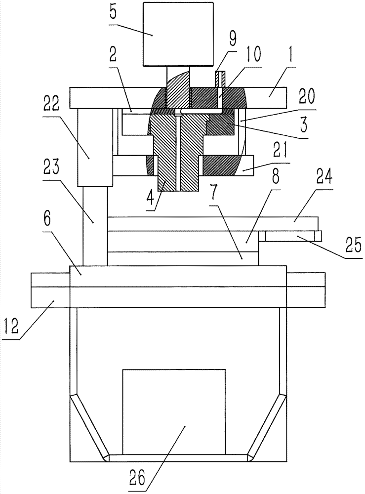
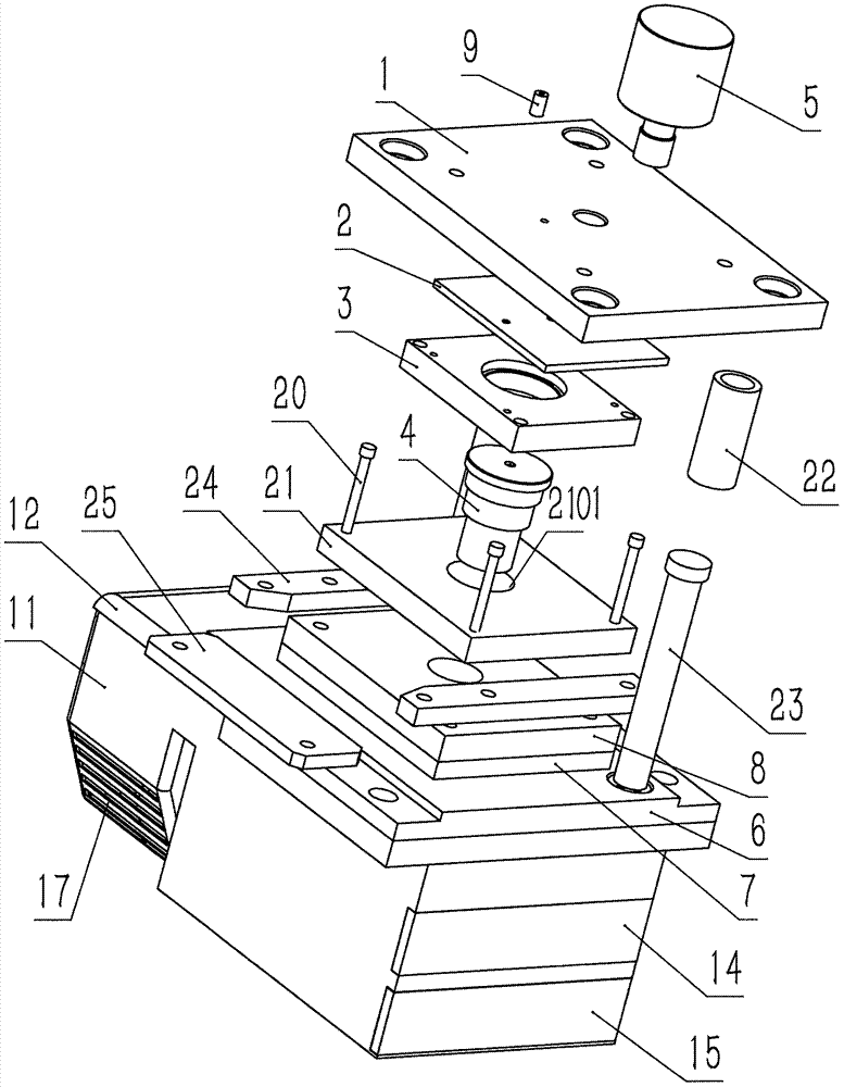
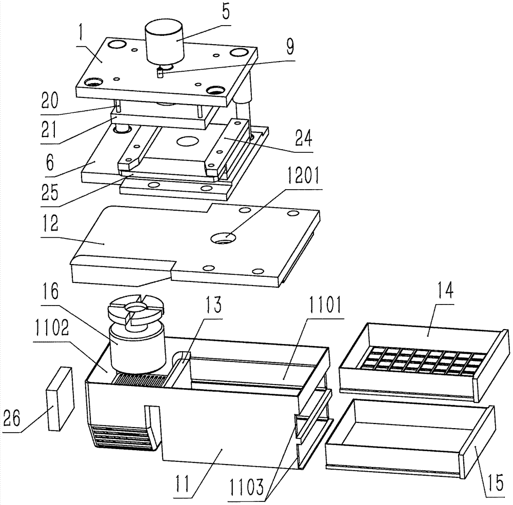
[0029] see Figure 1-5 , the present invention provides a technical solution: a punching die for collecting punched waste, including an upper die assembly and a lower die assembly group, the upper die assembly includes an upper die base 1, an upper backing plate 2, a punching die A sub-fixing plate 3 and a punch 4, the upper surface of the upper die base 1 is fixed with a driving device 5, the punch fixing plate 3 is installed on the lower surface of the upper...


PUM


Abstract

The invention discloses a punching die for collecting punched waste, which comprises an upper die assembly and a lower die assembly. The upper die assembly includes an upper die base, an upper backing plate, a punch fixing plate, and a punch. A driving device is installed and fixed on the upper surface of the upper die base, the punch fixing plate is installed on the lower surface of the upper die base, and the upper backing plate is installed on the upper die base and the punch fixing plate Between, the punch is installed on the punch fixing plate, the lower mold assembly includes a lower die base, a lower backing plate, a lower die, and the lower die is installed on the lower die base On the surface, the lower backing plate is installed between the lower die and the lower die base; a compressed air joint is installed on the upper die base, and the upper die base, the upper backing plate, and the punch are provided with a The blowing channel communicated with the compressed air joint; the compressed air blows off the generated waste through the blowing channel to prevent the work of the punching die from being affected.

Description

technical field [0001] The invention relates to the technical field of punching dies, in particular to a punching die for collecting punched waste. Background technique [0002] Generally, the punching die consists of upper and lower mold bases. The upper mold base is equipped with a punch (punch), and the lower mold base is equipped with a die. The drive system pushes the upper mold base to move the punch down along the guide column, so as to The die is matched to apply a shear force to the material to cause plastic deformation, cut off excess material, and produce a through hole. In terms of waste removal, a middle hole is generally formed at the mating part of the die and the punch. When the material is cut off, the waste material falls through the middle hole to the waste collection box at the bottom of the mold base by using its own weight. However, due to the existence of the bounce problem, the waste is easy to accumulate in the middle hole and cannot slide down smoo...

Claims


Application Information

Patent Timeline
Patent Type & Authority Applications(China)
IPC IPC(8): B21D28/34B21D43/20B21D45/00
CPCB21D28/34B21D43/20B21D45/00
Inventor 潘剑波
Owner NINGBO ZHENHAI YONGDING FASTENER
Why Eureka
Try Eureka