Device for bridge construction

A bridge and rotating shaft technology, applied in the field of bridge construction devices, can solve the problems of difficult maintenance, complex internal structure, and inability to pour out in batches, so as to improve work efficiency, facilitate operation, and improve automation control rate Effect

Active Publication Date: 2017-11-28
乐科工业设备有限公司
View PDF5 Cites 0 Cited by
  • Summary
  • Abstract
  • Description
  • Claims
  • Application Information

AI Technical Summary

Problems solved by technology

[0002] In the process of bridge construction, a large amount of concrete needs to be used. Generally, sand, stone, water, etc. are mixed in proportion to produce concrete at the construction site. The existing concrete mixer is huge, the internal structure is complex, and maintenance is difficult. It is difficult to move. In addition, it is difficult to control the amount of concrete poured out by these mixers. They are often poured out all at once instead of in batches, which cannot meet the needs of construction.

Method used


Image

  • Device for bridge construction
  • Device for bridge construction
  • Device for bridge construction

Examples


Embodiment Construction

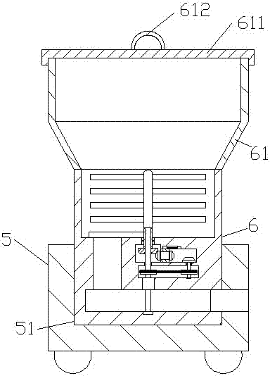
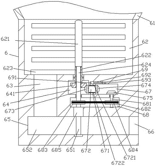
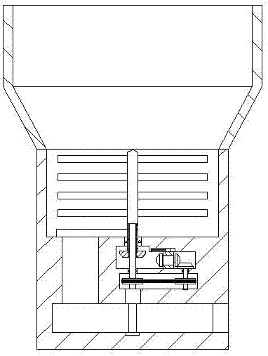
[0018] like Figure 1-Figure 4 As shown, a bridge construction device of the present invention comprises a base 5 and a concrete box 6, the top tail end of the right side of the base 5 is provided with a box groove 51, and the concrete box 6 is installed in the box groove 51 And fixedly connected, the top of the concrete box 6 is provided with a funnel 61, the concrete box 6 below the bottom of the funnel 61 is provided with a stirring chamber 62, and the inner bottom wall on the left side of the stirring chamber 62 is provided with a downward The excavation opening 63 that is extended, the bottom of the excavation opening 63 is extended and the tail end is connected with a batch chamber 65 that is extended to the right, and the concrete box 6 below the center of the mixing chamber 62 is provided with a first The conduction chamber 64, the rotation sleeve 622 extending up and down in the concrete box 6 between the first conduction chamber 64 and the mixing chamber 62 is connec...


PUM


Abstract

The invention discloses a device for bridge construction. The device comprises a base and a concrete box; a box groove is formed in the tail end of the top of the right side of the base; the concrete box is arranged in the box groove and is fixedly connected with the box groove; a hopper is arranged at the top of the concrete box; a mixing cavity is formed in the part, below the bottom of the hopper, of the concrete box; a soil discharge port extending downwards is formed in the inner bottom wall of the left side of the mixing cavity; a batching cavity extending rightwards penetrates through the extending tail end of the bottom of the soil discharge port; a first conveying and guide cavity is formed in the part, below the middle of the mixing cavity, of the concrete box; a rotating shaft sleeve extending vertically is connected with the interior, between the first conveying and guide cavity and the mixing cavity, of the concrete box in a rotary matching manner; the extending tail end of the top of the rotating shaft sleeve stretches into the mixing cavity; and blocking connecting plates are fixedly arranged on the outer surface of the left side, stretching into the mixing cavity, of the rotating shaft sleeve. The device is simple in structure and convenient to operate, the time and labor are saved during use, the soil discharge effect is improved, and the workload of operation personnel is reduced.

Description

technical field [0001] The invention relates to the field of bridges, in particular to a bridge construction device. Background technique [0002] In the process of bridge construction, a large amount of concrete needs to be used. Generally, sand, stone, water, etc. are mixed in proportion to produce concrete at the construction site. The existing concrete mixer is huge, the internal structure is complex, and maintenance is difficult. It is difficult to move. In addition, it is difficult for these mixers to control the pouring amount when pouring out concrete. They often pour out all at one time instead of batches, which cannot meet the needs of construction. . Contents of the invention [0003] The technical problem to be solved by the present invention is to provide a device for bridge construction, which can solve the above-mentioned problems in the prior art. [0004] The present invention is achieved through the following technical solutions: a device for bridge con...

Claims


Application Information

Patent Timeline
Patent Type & Authority Applications(China)
IPC IPC(8): B28C5/16B28C5/08
CPCB28C5/0806B28C5/0818B28C5/0893B28C5/16
Inventor 方基清
Owner 乐科工业设备有限公司
Why Eureka
Try Eureka