
Subsurface fluid carbon dioxide continuous on-line monitoring system and monitoring method

A carbon dioxide and underground fluid technology, applied in the direction of measuring devices, instruments, scientific instruments, etc., can solve the problems of poor measurement stability, low accuracy, and difficult to guarantee the accuracy of measurement values, and achieve good anti-interference, improve accuracy, good stability effect

Active Publication Date: 2020-05-12
杭州超钜科技有限公司
View PDF14 Cites 0 Cited by
  • Summary
  • Abstract
  • Description
  • Claims
  • Application Information

AI Technical Summary

Problems solved by technology

But CO 2 The rapid measurement tube method can only be applied to fault gas observation, which needs to be replaced every day, and the measured value can be read manually. It can only test the cumulative amount of carbon dioxide, and cannot reflect the real-time change of carbon dioxide concentration. also difficult to guarantee
Measurement of CO by Infrared Spectroscopy 2 High precision, capable of continuous analysis, has been widely used in industry, agriculture, environmental protection and other fields, but it is less used in earthquake prediction, and its applicability to underground fluid observation objects is poor, especially in high humidity observation environments Medium does not have application possibility, poor measurement stability and low accuracy

Method used


Image

  • Subsurface fluid carbon dioxide continuous on-line monitoring system and monitoring method
  • Subsurface fluid carbon dioxide continuous on-line monitoring system and monitoring method
  • Subsurface fluid carbon dioxide continuous on-line monitoring system and monitoring method

Examples


Embodiment

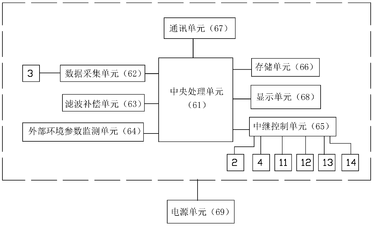
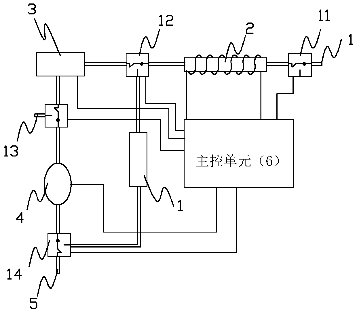
[0019] Embodiment: the underground fluid carbon dioxide continuous on-line monitoring system of the present embodiment, such as figure 1 As shown, it includes an air inlet 1, a recoverable dehumidification pipe 2, an array infrared carbon dioxide sensor 3, an electromagnetic pump 4, an air outlet 5, a dry filter pipe 7, a first electromagnetic valve 11, a second electromagnetic valve 12, and a third electromagnetic valve. The valve 13, the fourth solenoid valve 14 and the main control unit 6, the first solenoid valve 11, the second solenoid valve 12, the third solenoid valve 13 and the fourth solenoid valve 14 are all three-way solenoid valves with two options, and the air inlet 1. The first solenoid valve 11, the recoverable dehumidification pipe 2, the second solenoid valve 12, the array infrared carbon dioxide sensor 3, the third solenoid valve 13, the solenoid pump 4, the fourth solenoid valve 14 and the air outlet 5 pass through the pipeline in sequence One end of the dry...


PUM


Abstract

The invention relates to a continuous online CO2 monitoring system and method for underground fluids. The continuous online CO2 monitoring system comprises a gas inlet, a first solenoid valve, a dehumidification restorable pipe, a second solenoid valve, an array type infrared CO2 sensor, a third solenoid valve, an electromagnetic pump, a fourth solenoid valve and a gas outlet which are connected sequentially through a pipeline, wherein one end of a drying and filtering pipe is connected with the second solenoid valve through the pipeline, and the other end of the drying and filtering pipe is connected with the fourth solenoid valve through the pipeline; the dehumidification restorable pipe, the array type infrared CO2 sensor, the electromagnetic pump and the four solenoid valves are electrically connected with a master control unit respectively. The monitoring method comprises the following steps: the master control unit controls a communication channel of the four solenoid valves, and a monitoring gas channel, a cleaning gas channel and a dehumidification restoring channel are formed. With adoption of the monitoring system and method, wide-range continuous monitoring of CO2 concentration in a high-humidity environment is realized, various filter and compensation means are adopted, the anti-interference performance is good, errors are reduced effectively, the monitoring precision is high, the stability is good, and effectiveness of earthquake prediction is improved.

Description

technical field [0001] The invention relates to an underground fluid carbon dioxide monitoring technology, in particular to an underground fluid carbon dioxide continuous on-line monitoring system and monitoring method. Background technique [0002] The deep part of the earth's crust contains a large number of pores and fissures filled with water, gas and other fluids. These fluids are important factors affecting the genesis and occurrence of earthquakes. The underground fluids located in the shallow part of the earth's crust are important precursor information carriers that can sensitively reflect the process of earthquake gestation and occurrence. , has a sensitive ability to reflect shocks. Use of CO spilled freely from the surface 2 and CO dissolved in water and adsorbed in soil 2 Monitoring and predicting earthquakes with changes in gas concentration is one of the methods of earthquake prediction that has been focused on in China in recent years. Since 1988, using CO...

Claims


Application Information

Patent Timeline
Patent Type & Authority Patents(China)
IPC IPC(8): G01N21/3504
CPCG01N21/3504
Inventor 王维平刘佳琪王成宇
Owner 杭州超钜科技有限公司
Learn More