Motor and method of controlling rotation speed of same

A speed control and motor technology, applied in the direction of a single motor speed/torque control, control system, motor control, etc., can solve problems such as line inconsistency, fan motor speed adjustment, increased motor cost and difficulty, etc.

Active Publication Date: 2017-11-28
SUNON ELECTRONICS (BEIHAI) CO LTD
View PDF5 Cites 4 Cited by
  • Summary
  • Abstract
  • Description
  • Claims
  • Application Information

AI Technical Summary

Problems solved by technology

Among them, as the duty cycle (DUTY CYCLE) of the control signal (such as PWM signal) increases, the ideal rotational speed curve C1 of the motor presents a linear trend, but the actual rotational speed curve C2 of the motor presents a nonlinear curve, and the actual rotational speed curve C2 and The linear shape of the ideal speed curve C1 is inconsistent, so that the speed of the fan motor cannot be adjusted directly using the duty cycle, and an additional speed signal compensation circuit is required to fine-tune the speed, which will increase the cost and difficulty of motor control

Method used


Image

  • Motor and method of controlling rotation speed of same
  • Motor and method of controlling rotation speed of same
  • Motor and method of controlling rotation speed of same

Examples


Embodiment Construction

[0035] In order to make the above-mentioned and other objects, features and advantages of the present invention more comprehensible, the preferred embodiments of the present invention are specifically cited below, together with the accompanying drawings, as follows:

[0036] The directional terms described throughout the present invention, such as front, back, left, right, upper (top), lower (bottom), inner, outer, side, etc., mainly refer to the directions of the drawings, and each directional term is only used The various embodiments of the present invention are used to assist in explaining and understanding the present invention, but are not intended to limit the present invention.

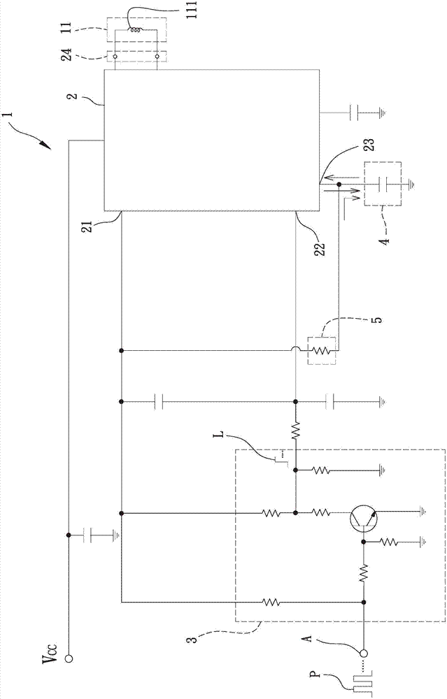
[0037] see figure 2 As shown, it is a schematic circuit diagram of the embodiment of the motor system of the present invention. Wherein, the system embodiment may include a motor 1 and a control unit 2, the control unit 2 is electrically connected to the motor 1, and is used to output signals...


PUM


Abstract

The invention relates to a motor and a method of controlling the rotation speed of the same, and aims to solve the problem that the rotation speed of a conventional motor is non-linear. The method can be applied to a control unit. The control unit is used to adjust the rotation speed of a motor. The method comprises the following steps: generating a logic signal by comparing the voltage value of a reference signal and the voltage value of an oscillation signal by the control unit so as to control the rotation speed of the motor; wherein the voltage value of the reference signal is generated by converting the work period of a pulse-width modulation signal, the waveform of the oscillation signal comprises a charging period and a discharging period, the time of the discharging period is longer than the time of the charging period, and the problem is solved by the abovementioned method.

Description

technical field [0001] The invention relates to a motor and a control method thereof; in particular, to a motor and a speed control method thereof. Background technique [0002] Existing motors can convert electrical energy into power output, so as to serve as a power source for fans and other devices. Taking fans as an example, the motor drives the blades to generate airflow, which can be used for air circulation or heat dissipation. [0003] Taking the existing fan motor as an example, the universal fan driver (fan driver ASIC) outputs a control signal to the coil of the motor, and cooperates with the induction component (such as the Hall component) to sense the state parameters of the motor operation, and then the rotor of the motor can be driven Rotate to output torque. [0004] see figure 1 As shown in , it is a schematic diagram comparing the actual speed curve of the existing motor with the ideal speed curve. Among them, as the duty cycle (DUTY CYCLE) of the contro...

Claims


Application Information

Patent Timeline
Patent Type & Authority Applications(China)
IPC IPC(8): H02P29/00H02P6/08
CPCH02P6/08H02P29/00H02P2205/07
Inventor 洪银树郭俊谷
Owner SUNON ELECTRONICS (BEIHAI) CO LTD
Why Eureka
Try Eureka