Vibration-damping device

一种隔振、安装构件的技术,应用在减振器、减振器-弹簧组合、弹簧/减震器等方向,达到抑制异常噪音、简单结构的效果

Active Publication Date: 2017-11-28
BRIDGESTONE CORP
View PDF7 Cites 1 Cited by
  • Summary
  • Abstract
  • Description
  • Claims
  • Application Information

AI Technical Summary

Problems solved by technology

[0003] However, in the vibration isolator, when, for example, a large load is input due to unevenness of the road surface, etc., and the hydraulic pressure of the main liquid chamber increases rapidly, the load is input in the opposite direction due to the rebound of the elastic body, etc., causing the main Liquid chamber depressurizes rapidly in some cases
As a result, cavitation occurs in which many air bubbles are generated in the liquid due to rapid decompression, and in some cases, abnormal noise is generated due to the collapse of the air pockets due to the collapse of the generated air bubbles

Method used


Image

  • Vibration-damping device
  • Vibration-damping device
  • Vibration-damping device

Examples


Embodiment Construction

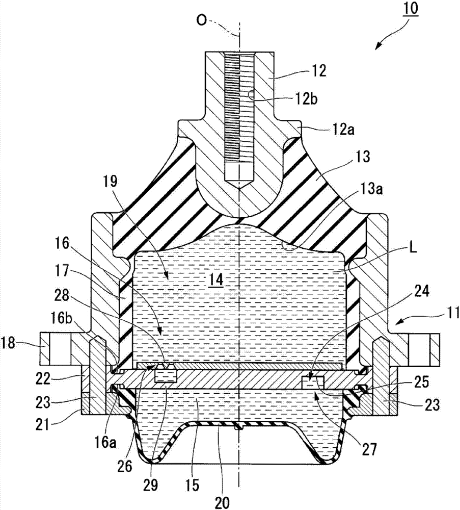
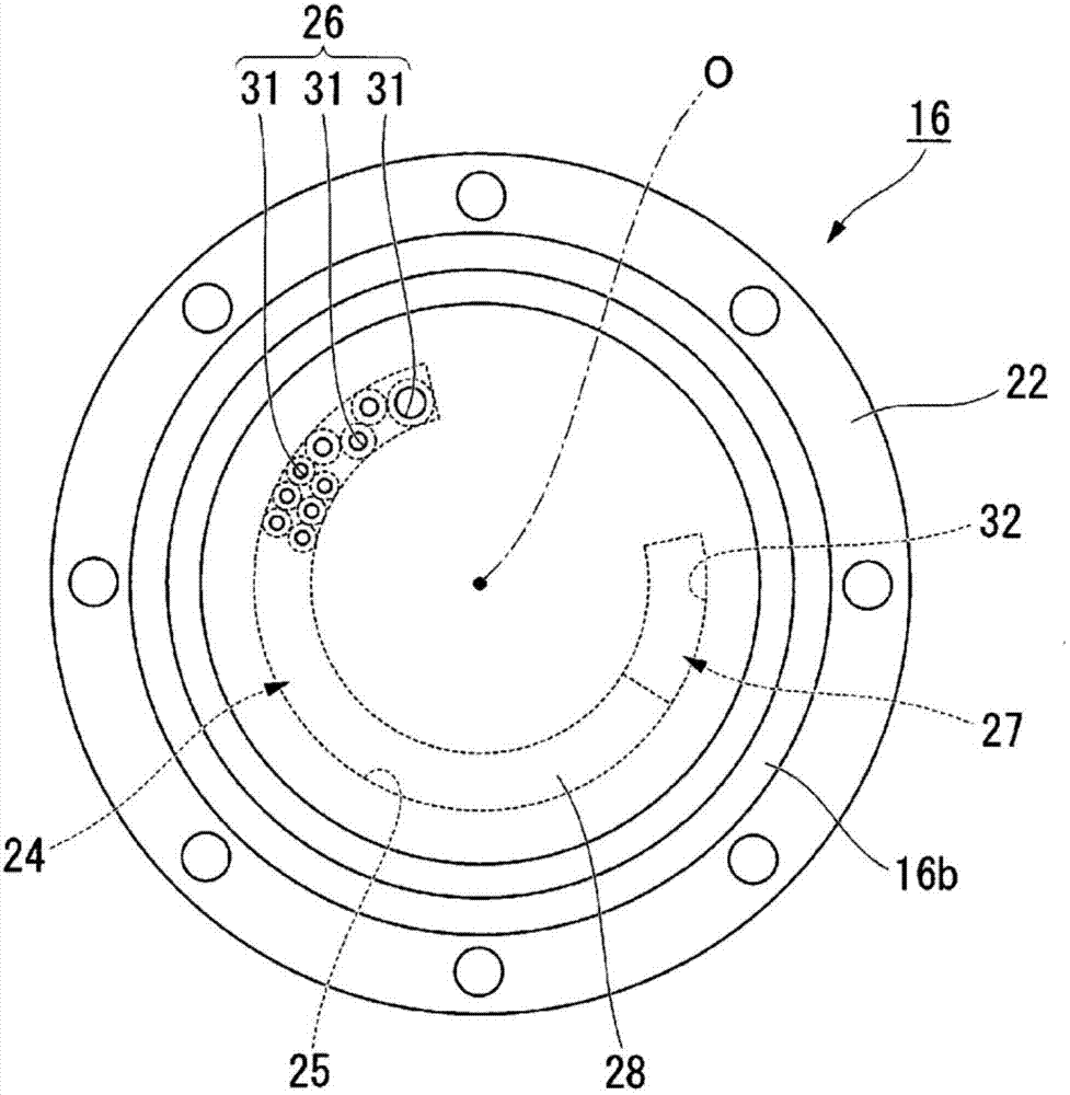
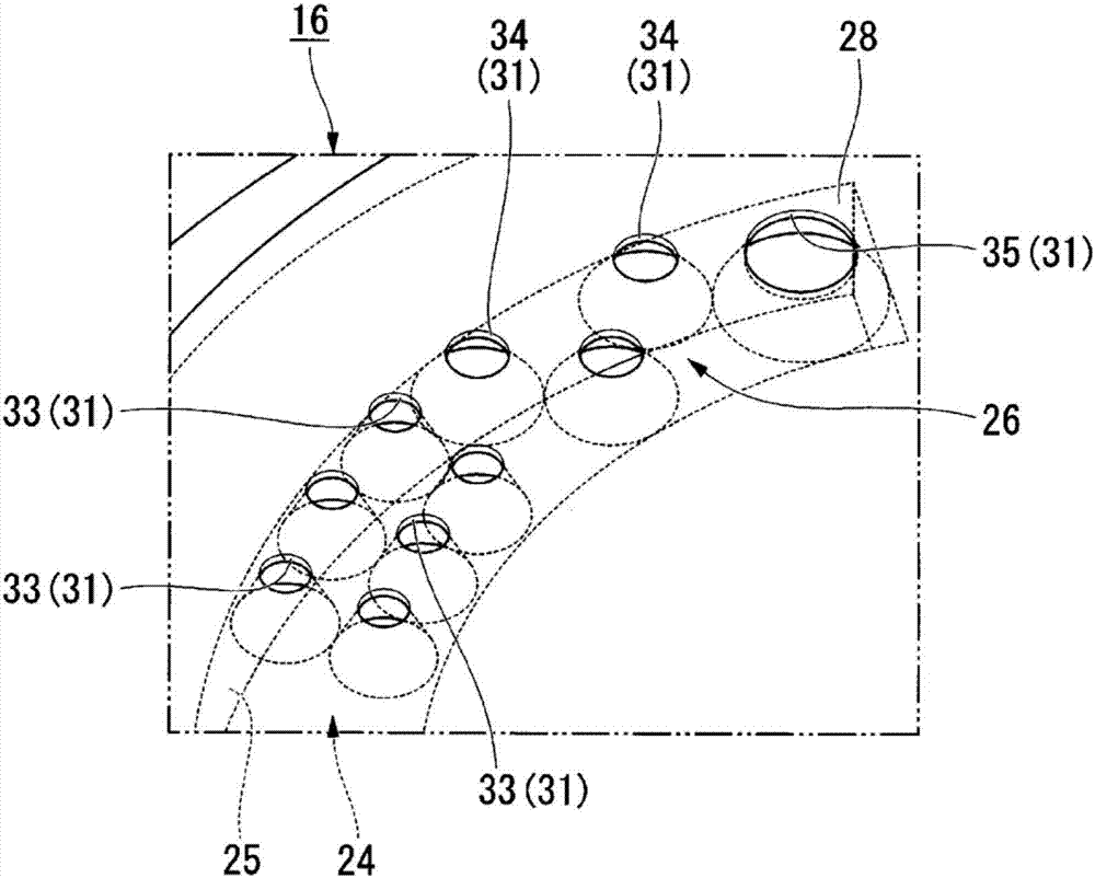
[0028] The following will be based on Figure 1 to Figure 3 Embodiments of the vibration isolation device according to the present invention will be described. Notice, figure 1 The shown reference numeral O (hereinafter simply referred to as "axis center O") denotes the central axis of the vibration isolator 10 (the central axis of the first mounting member 11 which will be described below). In addition, the direction along the axis O is set as "axial direction" (the axial direction of the first attachment member 11 ). In the plan view of the vibration isolator 10 viewed from the axial direction, the direction perpendicular to the axis O is defined as the "radial direction" (the radial direction of the first mounting member 11), and the direction around the axis O is defined as Let it be "circumferential direction" (circumferential direction of the first mounting member 11).

[0029] like figure 1 As shown, the vibration isolation device 10 includes: a cylindrical first mo...


PUM


Abstract

The present invention relates to a liquid-sealed vibration-damping device (10). This vibration-damping device (10) is configured such that a limiting passage (24) is provided with: a body passage (25) disposed within a partition member (16); a first communication section (26) for connecting the body passage (25) and a first liquid chamber (14); and a second communication section (27) for connecting the body passage (25) and a second liquid chamber (12), and the first communication section (26) and / or the second communication section (27) is provided with a plurality of openings (31).

Description

technical field [0001] The present invention relates to a vibration isolating device which is suitable for use in, for example, automobiles, industrial machines, etc., and which absorbs and attenuates the vibration of a vibration generating part such as an engine or the like. Priority is claimed from Japanese Patent Application Japanese Patent Application No. 2015-056079 filed on March 19, 2015, the contents of which are incorporated herein by reference. Background technique [0002] In the related art, such a vibration isolating device includes: a cylindrical first mounting member connected to one of the vibration generating part and the vibration receiving part; a second mounting member connected to the vibration generating part and the vibration receiving part the other one; an elastic body configured to connect the two mounting members; and a partition member configured to partition the liquid-enclosed liquid chamber in the first mounting member into a main liquid chambe...

Claims


Application Information

Patent Timeline
Patent Type & Authority Applications(China)
IPC IPC(8): F16F13/10
CPCF16F13/107F16F13/10
Inventor 永泽正和植木哲长岛康寿之
Owner BRIDGESTONE CORP
Why Eureka
Try Eureka