
A decorative panel cutting device for interior decoration

A technology for cutting devices and decorative panels, applied in the direction of feeding devices, positioning devices, manufacturing tools, etc., can solve the problems of single function of sheet cutting equipment, poor sheet cutting quality, and low sheet cutting efficiency, and achieve wide application range and cutting size Adjustable, easy-to-operate effects

Active Publication Date: 2019-04-19
深圳市中为装饰工程有限公司
View PDF2 Cites 0 Cited by
  • Summary
  • Abstract
  • Description
  • Claims
  • Application Information

AI Technical Summary

Problems solved by technology

[0005] The technical problem to be solved by the present invention is to provide a decorative board cutting device for interior decoration, so as to solve the single function of the board cutting equipment caused in the prior art, manual compaction is required during the cutting process of the board, and the Among them, the plate is easy to tilt, resulting in low cutting efficiency and poor cutting quality of the plate, limited use and many other defects

Method used


Image

  • A decorative panel cutting device for interior decoration
  • A decorative panel cutting device for interior decoration
  • A decorative panel cutting device for interior decoration

Examples


Embodiment 2

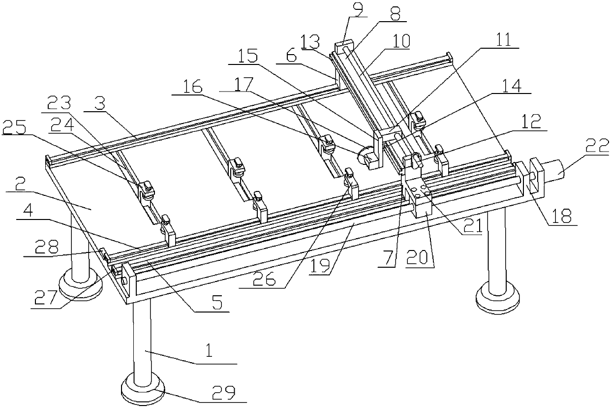
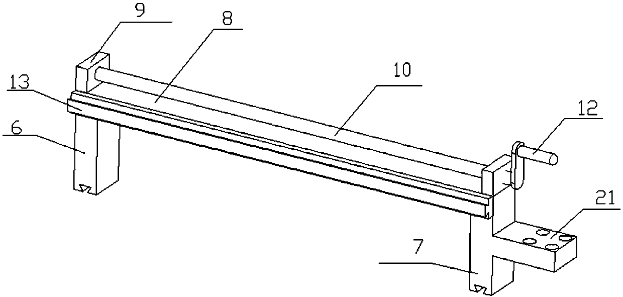
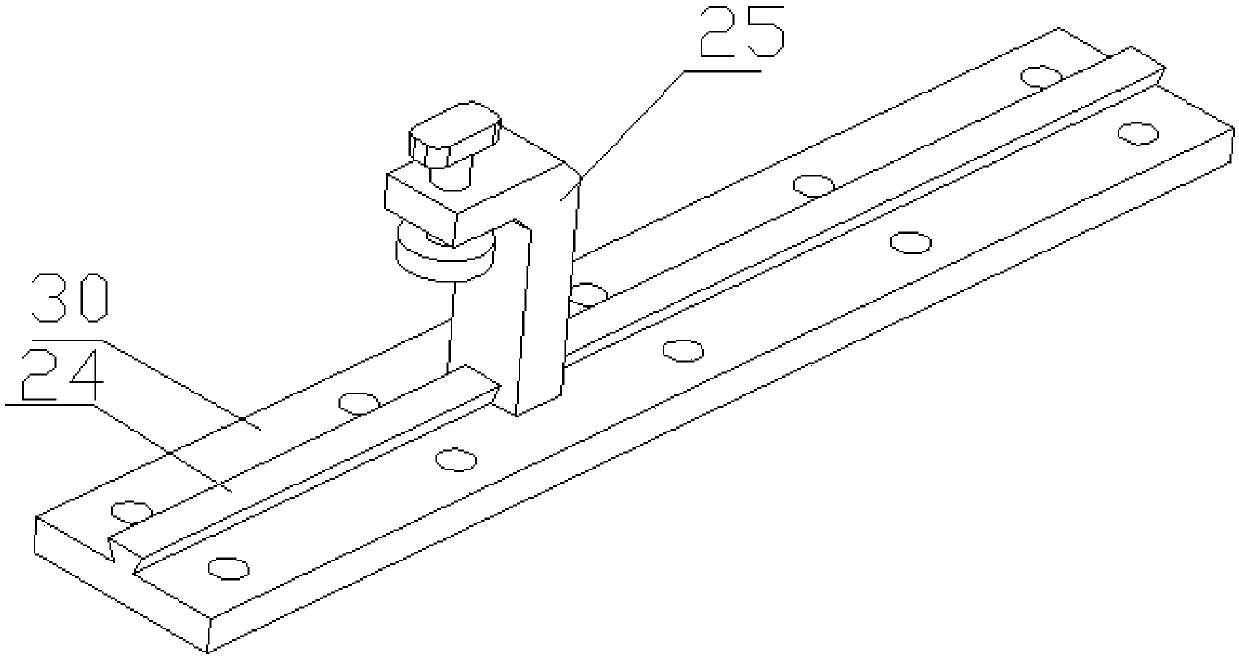
[0034] figure 1 , figure 2 , image 3 and Figure 4 The specific embodiment of the present invention is shown: a decorative board cutting device for interior decoration, including four legs 1 and a workbench 2 arranged on the legs 1, the workbench 2 is provided with first guide rails arranged in parallel 3. The second guide rail 4 and the third guide rail 5, the second guide rail 4 is arranged between the first guide rail 3 and the third guide rail 5, and the first guide rail 3 and the third guide rail 5 are respectively provided with the first The first sliding seat 6 and the third sliding seat 7 that are slidably matched between the guide rail 3 and the third guide rail 5, a connecting plate 8 is arranged between the first sliding seat 6 and the third sliding seat 7, and a connecting plate 8 is provided on the connecting plate 8 There is a cutting motor 16, the position of the cutting motor 16 on the connecting plate 8 is adjustable, the output shaft of the cutting motor...

Embodiment 3

[0038] figure 1 , figure 2 , image 3 , Figure 4 , Figure 5 and Figure 6 The specific embodiment of the present invention is shown: a decorative board cutting device for interior decoration, including four legs 1 and a workbench 2 arranged on the legs 1, the workbench 2 is provided with first guide rails arranged in parallel 3. The second guide rail 4 and the third guide rail 5, the second guide rail 4 is arranged between the first guide rail 3 and the third guide rail 5, and the first guide rail 3 and the third guide rail 5 are respectively provided with the first The first sliding seat 6 and the third sliding seat 7 that are slidably matched between the guide rail 3 and the third guide rail 5, a connecting plate 8 is arranged between the first sliding seat 6 and the third sliding seat 7, and a connecting plate 8 is provided on the connecting plate 8 There is a cutting motor 16, the position of the cutting motor 16 on the connecting plate 8 is adjustable, the output ...


PUM


Abstract

The invention discloses a cutting device of decorative sheets for indoor decoration and relates to the field of cutting equipment. The cutting device comprises four supporting legs and a workbench. A first guide rail, a second guide rail and a third guide rail are arranged on the workbench. The first guide rail and the third guide rail are provided with a first sliding base and a third sliding base correspondingly. A connecting plate is arranged between the first sliding base and the third sliding base. A cutting motor is arranged on the connecting plate and provided with a cutting cutter head. The two ends of the third guide rail are provided with fixing bases. A first lead screw is arranged between the fixing bases. A driving motor is further arranged on one of the fixing bases and connected with one end of the first lead screw. A first nut base is arranged on the first lead screw. A transverse plate is arranged on the side wall of the third sliding base and connected with the first nut base. A plurality of longitudinal adjusting pressing mechanism is arranged on the second guide rail. A plurality of rectangular grooves are formed in the workbench. A bottom plate is arranged at the bottom of each rectangular groove. Fourth guide rails are arranged on the bottom plates. Transverse adjusting pressing mechanisms are arranged on the fourth guide rails. The cutting device is wide in application range, good in cutting quality and high in efficiency.

Description

technical field [0001] The invention relates to the field of equipment related to interior decoration, in particular to a decorative board cutting device for interior decoration. Background technique [0002] In the process of interior decoration design, some decorative panels need to be cut according to the size first, which requires the use of cutting equipment. However, traditional cutting machines need to be pressed manually during the cutting process of the panels, and during the cutting process , The plate is easy to tilt, resulting in low cutting efficiency and poor cutting quality of the plate, and the use is limited. The traditional cutting machine can no longer meet the needs. [0003] In view of the above problems, some improvements have been made in the prior art. For example, the invention with the publication number CN 106003188 A discloses a plate cutting device, which includes a main body. A cutting cavity is formed in the main body along the conveying direct...

Claims


Application Information

Patent Timeline
Patent Type & Authority Patents(China)
IPC IPC(8): B23D79/00B23Q5/40B23Q3/06B23Q1/26
CPCB23D79/00B23Q1/26B23Q3/062B23Q3/069B23Q5/40
Inventor 袁荣张福敏
Owner 深圳市中为装饰工程有限公司
Learn More