Eureka AIR delivers breakthrough ideas for toughest innovation challenges, trusted by R&D personnel around the world.

Automobile Front Axle with Side Impact Energy-absorbing Structure

An energy-absorbing structure, the technology of the front axle of a car, applied to axles, wheels, vehicle parts, etc., can solve problems such as poor safety, achieve good side impact resistance, and increase the effect of elements involved in energy absorption

Active Publication Date: 2020-09-11
XINYI XIYI ADVANCED MATERIALS RES INST OF IND TECH CO LTD
View PDF7 Cites 0 Cited by
  • Summary
  • Abstract
  • Description
  • Claims
  • Application Information

AI Technical Summary

Problems solved by technology

[0004] The invention provides an automobile front axle with a side impact energy-absorbing structure that can absorb side impact energy without vehicle frame collapse and deformation during a side impact, and solves the problem of vehicle body collapse and energy absorption in an existing automobile side impact The problem of poor security caused by

Method used


Image

  • Automobile Front Axle with Side Impact Energy-absorbing Structure
  • Automobile Front Axle with Side Impact Energy-absorbing Structure
  • Automobile Front Axle with Side Impact Energy-absorbing Structure

Examples


Embodiment 1

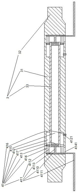
[0019] Embodiment one, see figure 1 , an automobile front axle provided with a side impact energy-absorbing structure, comprising a front axle 3 .

[0020] The front axle 3 includes a cross bar 31 and two suspension arms 32 located at both ends of the cross bar. A side impact energy-absorbing structure 41 is respectively provided at the left and right ends of the cross bar 31 .

[0021] The side impact energy-absorbing structure 41 includes a drive frame 411 , a cylinder 412 , a compression piston 413 , a first frictional energy-dissipating cylinder 414 and a second frictional energy-dissipating cylinder 415 .

[0022] A pipe body 33 is slidingly sealed in the cross bar 31 . The pipe body 33 extends in the left-right direction. The inner space of the pipe body 33 constitutes a total of two second frictional energy dissipation cylinders 415 of the two side impact energy absorbing structures 41 . A third friction layer is provided on the inner peripheral surface of the secon...

Embodiment 2

[0029] Embodiment two, the difference with embodiment one is:

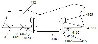
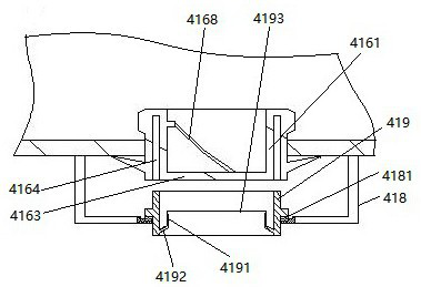
[0030] see image 3 , the inner peripheral surface of the inner tube 4161 is provided with fan blades 4168 that guide the sealing head 416 to rotate when the fluid flows through the inner tube. The crossbar 31 is also provided with a support frame 518 . The supporting frame 418 is rotatably connected with a connecting sleeve 419 through a plane bearing 4181 . The connecting sleeve 419 is connected with an annular blade 4191 . A limiting portion 4192 is formed between the annular blade 4191 and the connecting sleeve 419 . The blade 4191 is provided with an annular cutting edge 4193 . The annular cutting edge 4193 is aligned with the bottom wall 4163 . The outer diameter of the blade 4191 is equal to the inner diameter of the inner circular tube 4161.

[0031] During use, if the sealing head 416 is ejected, before the annular cutting edge 4193 contacts the bottom wall 4163, the connecting sleeve 419 is first i...


PUM


Abstract

The present invention relates to a front axle of an automobile. An automobile front axle equipped with a side impact energy-absorbing structure, including a front axle, the front axle includes a cross bar and two cantilevers located at both ends of the cross bar, and a side impact energy-absorbing arm is provided at the left and right ends of the slide bar structure, the side impact energy-absorbing structure includes a cylinder extending in the left-right direction, a compression piston sealed and slidably connected to one end of the cylinder, and a drive frame for driving the compression piston. Extended elongated avoidance hole, the drive frame is penetrated in the elongated avoidance hole, the other end of the cylinder is provided with a spray hole, and the spray hole is connected with a The sealing head is pressed out by the gas in the cylinder when the set value is reached. The invention provides an automobile front axle with a side impact energy-absorbing structure that can absorb side impact energy without vehicle frame collapse and deformation during side impact, and solves the problem that the vehicle body collapses and absorbs energy when a side impact occurs. lead to poor security problems.

Description

technical field [0001] The invention relates to an automobile front axle, in particular to an automobile front axle provided with a side impact energy-absorbing structure. Background technique [0002] The front axle of the car is used to install the front wheels, support the weight of the front of the car, and connect with the frame with the front suspension. In Chinese patent application number 2011201792654, the authorized announcement date is December 28, 2011, and promptly discloses a kind of automobile front axle of existing structure in the patent document of name " automobile front axle assembly ". The front axle of the automobile includes a cross bar and two cantilever arms. A vehicle frame supporting part is respectively arranged at both ends of the cross bar. A cantilever is respectively connected to both ends of the cross bar. The cantilever is provided with a king pin hole. During use, the steering knuckle is connected with the front axle through the kingpin pa...

Claims


Application Information

Patent Timeline
Patent Type & Authority Patents(China)
IPC IPC(8): B60B35/00
CPCB60B35/00B60B35/003
Inventor 陈学福何伟
Owner XINYI XIYI ADVANCED MATERIALS RES INST OF IND TECH CO LTD
Why Eureka
Eureka Blog
Learn More