A supporting device between girders of a maglev turnout

A technology of support device and turnout beam, which is applied in the directions of roads, tracks, moving rail parts, etc., can solve the problems of vibration, affecting the service life of the turnout, and the vertical displacement of the turnout beam cannot be well limited. , to achieve the effect of avoiding the service life and reducing the gap

Active Publication Date: 2020-06-26
CHINA RAILWAY CONSTR HEAVY IND
View PDF6 Cites 0 Cited by
  • Summary
  • Abstract
  • Description
  • Claims
  • Application Information

AI Technical Summary

Problems solved by technology

Due to processing and assembly errors, there is a certain gap between the contact surfaces of the slider and the lower support in the existing inter-beam support device, so that the vertical displacement of the turnout beam connected to the upper support cannot be well restricted. When the maglev train passes, it will generate vibration, which will affect the ride comfort and the service life of the switch

Method used


Image

  • A supporting device between girders of a maglev turnout
  • A supporting device between girders of a maglev turnout
  • A supporting device between girders of a maglev turnout

Examples


Embodiment Construction

[0023] The present invention will be further described in detail below in conjunction with the accompanying drawings and specific embodiments, but the protection scope of the present invention is not limited thereby.

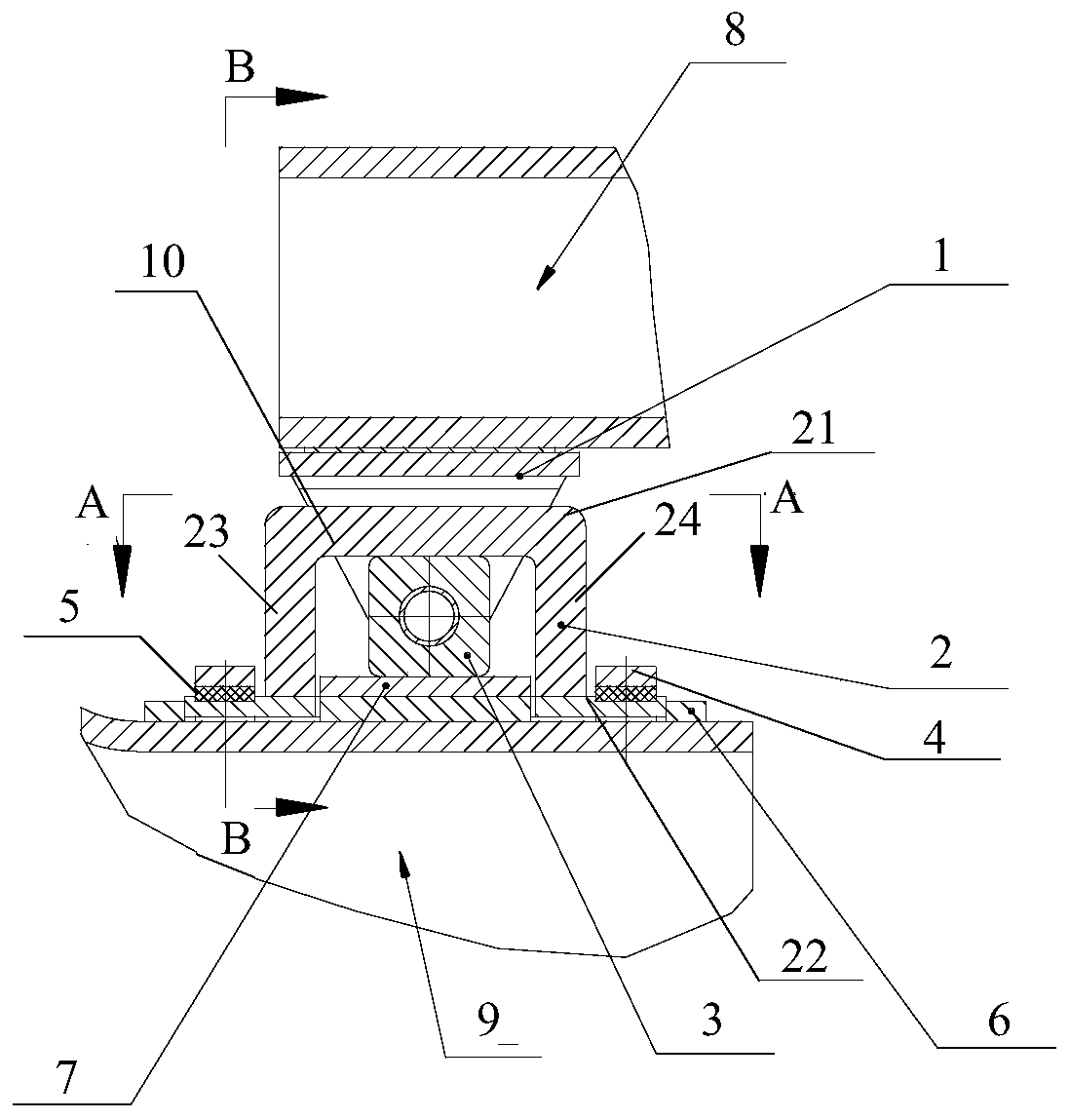
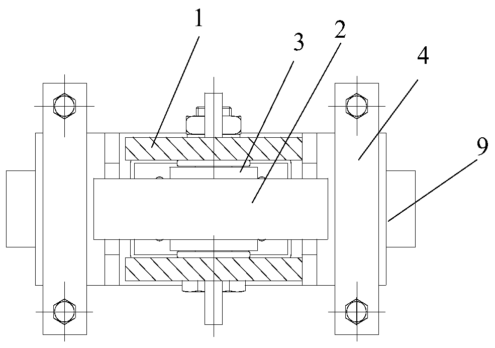
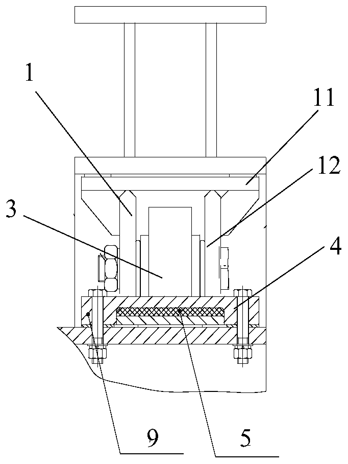
[0024] figure 1 Schematically shows the front view cross-sectional structure of the support device 10 of the embodiment of the present invention. figure 2 A top view cross-sectional structure of the support device 10 according to the embodiment of the present invention is schematically shown. image 3 Schematically shows the cross-sectional structure of the support device 10 in the embodiment of the present invention as viewed from the left. Such as Figure 1 to Figure 3 As shown, the support device 10 according to the embodiment of the present invention includes an upper support 1 connected to the upper turnout beam 8 and a lower support 2 connected to the lower turnout beam 9, and is connected to the upper support 1 in a detachable manner. slider 3. The l...


PUM


Abstract

The invention provides a supporting device located between magnetic levitation turnout beams. The supporting device located between the magnetic levitation turnout beams comprises an upper supporting base, a lower supporting base and a sliding block, wherein the upper supporting base is connected with the upper turnout beam, the lower supporting base is connected with the lower turnout beam, and the sliding block is detachably connected with the upper supporting base. The lower supporting base is arranged on the sliding block and fixedly connected with the lower turnout beam in a detachable mode through press plates. The sliding block can slide and rotate relative to the lower turnout beam which is connected with the lower supporting base. The displacement of the turnout beams in the vertical direction can be limited, and therefore the problem that due to the fact that vibration is generated when a maglev train passes through a turnout, the riding comfort and the service life of the turnout are affected is solved.

Description

technical field [0001] The invention belongs to the technical field of maglev turnouts, and in particular relates to a support device between girders of maglev turnouts. Background technique [0002] As an important part of the medium and low speed maglev traffic, the medium and low speed maglev turnout is the line change equipment of the maglev line. The turnout adopts a segmental structure, mainly including fixed-end stacking beams, first driven beams, second driven beams, active beams, and movable end stacking beams. The turnout beams are connected by inter-beam support devices. During the transition of the turnout, the two turnout beams rotate relative to each other, and the force is transmitted by the support device, and the position is limited. In order to enable the two turnout beams to rotate relatively, the supporting device between the beams used in the existing medium and low-speed maglev turnouts adopts a rigid connecting seat with a gap. Due to processing and ...

Claims


Application Information

Patent Timeline
Patent Type & Authority Patents(China)
IPC IPC(8): E01B25/34
CPCE01B25/34E01B2202/042
Inventor 周文方永东张亚军李欢李东辉
Owner CHINA RAILWAY CONSTR HEAVY IND
Why Eureka
Try Eureka