
Self-elevating drilling platform pitching pile simulation test loading device and method

A self-elevating platform and drilling platform technology, which is applied in the direction of foundation structure test, construction, foundation structure engineering, etc., can solve the problem that it is difficult to realize segmental continuous loading of piles, poor design of preload, different, It may range from a few tons to a dozen tons, or even more than 20 tons.

Inactive Publication Date: 2017-12-01
CNOOC TIANJIN BRANCH +1
View PDF3 Cites 4 Cited by
  • Summary
  • Abstract
  • Description
  • Claims
  • Application Information

AI Technical Summary

Problems solved by technology

However, this type of top static pile pressing method is not the same as the preloading method of pile insertion on offshore jack-up drilling platforms, it is difficult to realize the simulation of segmental continuous loading in pile insertion operation, and the preload cannot be well designed
Moreover, different similarity ratios will be used in the simulation test, resulting in different test loads, which may range from a few tons to a dozen tons, or even more than 20 tons; usually, the top loading method used by static pressure piles is not suitable for different sizes of offshore piles. Experimental Research on Pile Insertion Regularity for Ton-level Loading

Method used


Image

  • Self-elevating drilling platform pitching pile simulation test loading device and method
  • Self-elevating drilling platform pitching pile simulation test loading device and method
  • Self-elevating drilling platform pitching pile simulation test loading device and method

Examples


Embodiment Construction

[0022] The present invention will be described in detail below in conjunction with the accompanying drawings and embodiments.

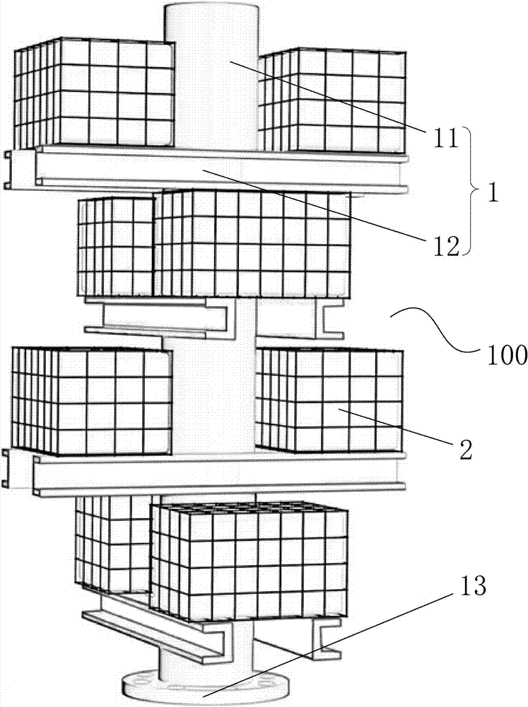
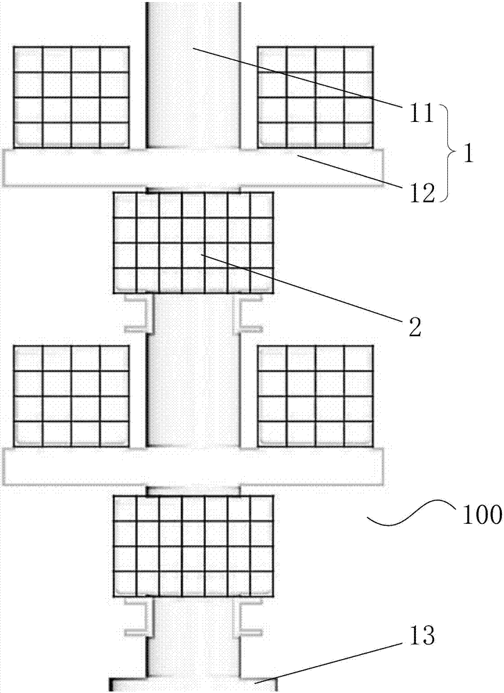
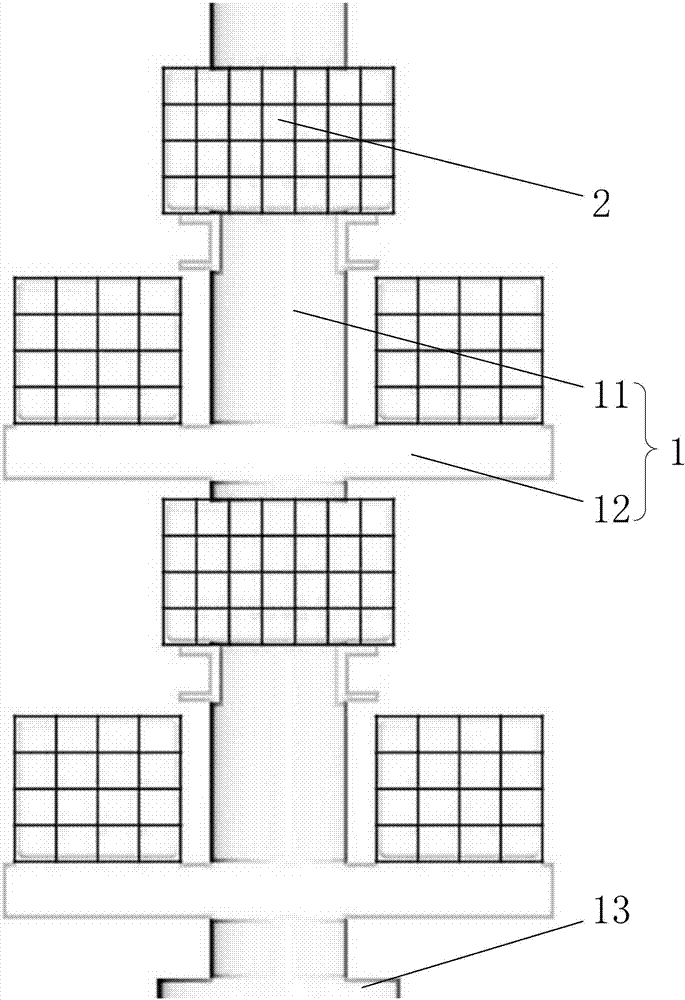
[0023] Such as Figure 1 to Figure 4 with Figure 7 As shown, a jack-up drilling platform piling simulation test loading device 100 provided by the present invention includes a loading steel frame 1 and a ballast water tank 2; The upper part of the leg 200 is fixedly connected, and a plurality of ballast water tanks 2 of the same volume are fixedly arranged on the loading steel frame 1 in layers and groups from top to bottom, and the ballast water tanks 2 of the same layer are symmetrically distributed on both sides of the loading steel frame 1. On the side, the ballast water tanks 2 adjacent to the upper and lower floors are vertically staggered.

[0024] In the above example, if Figure 5 with Figure 7 As shown, the loading steel frame 1 includes a central steel column 11 and a steel beam 12 . The central steel column 11 is a thick-walled stee...


PUM


Abstract

The invention relates to a self-elevating drilling platform pitching pile simulation test loading device and method. The self-elevating drilling platform pitching pile simulation test loading device comprises a loading steel frame used for being fixedly connected with the upper part of pile legs of a test simulation self-elevating platform and a plurality of ballast water tanks of the same volume. The multiple ballast water tanks are fixedly and hierarchically arranged on the loading steel frame from top to bottom in the height direction of the loading steel frame. The ballast water tanks on the same layer are symmetrically distributed on the two sides of the same elevation position of the loading steel frame. The ballast water tanks of the adjacent upper and lower layers are perpendicularly arranged at two different elevation positions of the loading steel frame in a staggered mode. According to the self-elevating drilling platform pitching pile simulation test loading device, the water tanks are evenly installed at the different positions of the pile legs used for a stimulation test, seawater or other fluid mediums of high density are pumped into the water tanks through a water pump according to different pumping speeds, dressing-capping-type splitting loading is conducted, a self-elevating drilling platform can be stimulated to complete preballasting operation be relying on ballast tank water taking-in well, and the high similarity is achieved.

Description

technical field [0001] The invention relates to a test loading device and method, in particular to a jack-up drilling platform pile insertion simulation test loading device and method. Background technique [0002] The jack-up drilling platform is one of the important drilling rig equipment in the process of offshore drilling, and is currently the main force of drilling equipment in waters with a water depth of less than 120 meters. The jack-up drilling platform stands in the shallow soil layer of the seabed on three or four steel structure legs with a length of tens of meters or even nearly 200 meters installed by itself. The cabin and deck attached to the legs can move along the piles. The length direction of the legs rises and falls vertically, so it is called a jack-up drilling platform. Different jack-up drilling platforms have different operating capabilities and load conditions, which determines that the design preload varies greatly; and the load-bearing area of ​​t...

Claims


Application Information

Patent Timeline
IPC IPC(8): E02D33/00
CPCE02D33/00E02D2300/0029
Inventor 谢仁军刘书杰周建良徐国贤吴怡焦金刚
Owner CNOOC TIANJIN BRANCH
Learn More