
Determining device and method of water permeability coefficient of concrete

A technology of water permeability coefficient and measuring device, which is applied in the direction of measuring device, permeability/surface area analysis, suspension and porous material analysis, etc. It can solve the problems of complex measuring device, measurement result error, unstable performance, etc., and achieve high measurement accuracy , the liquid level is fast and stable, and the effect of continuous data recording

Inactive Publication Date: 2017-12-01
云南建投绿色高性能混凝土股份有限公司
View PDF7 Cites 3 Cited by
  • Summary
  • Abstract
  • Description
  • Claims
  • Application Information

AI Technical Summary

Problems solved by technology

[0005] The purpose of the present invention is to provide a concrete water permeability coefficient measuring device and its method, which can solve the problems of complex traditional measuring devices, cumbersome operation during use, unstable performance and large error in measurement results

Method used


Image

  • Determining device and method of water permeability coefficient of concrete
  • Determining device and method of water permeability coefficient of concrete
  • Determining device and method of water permeability coefficient of concrete

Examples


Embodiment 1

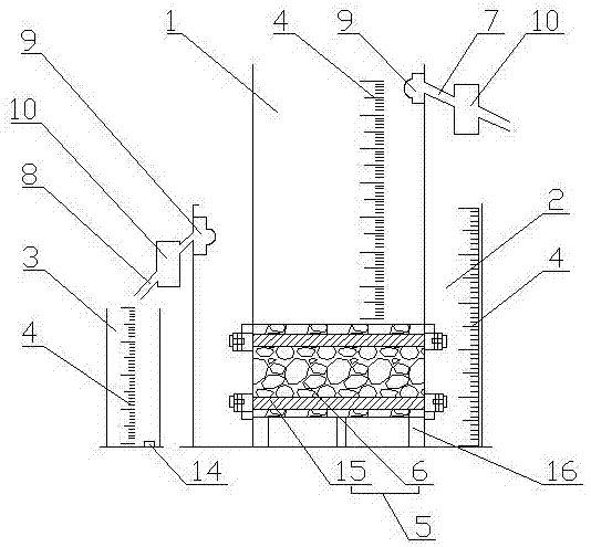
[0043] like figure 1 and 2 As shown, it includes a transparent cylinder 1, an overflow tank 2 and a measuring cylinder 3. The outer walls of the transparent cylinder 1, overflow tank 2 and measuring cylinder 3 are all engraved with a scale 4, and the transparent cylinder 1 is vertically arranged in the overflow tank 2, the upper and lower ends of the transparent cylinder 1 are open, wherein the lower opening of the transparent cylinder 1 is provided with a concrete sealing and fixing device 5; the outer wall of the upper part of the transparent cylinder 1 is provided with a cylinder overflow port 7, and the overflow The outer wall of the tank 2 is provided with an overflow tank overflow port 8, wherein the measuring cylinder 3 is arranged below the overflow tank overflow port 8, and the cylinder overflow port 7 and the overflow tank overflow port 8 are sequentially installed with Rotameter 9 and liquid flow automatic controller 10; Liquid flow automatic controller 10 is made ...

Embodiment 2

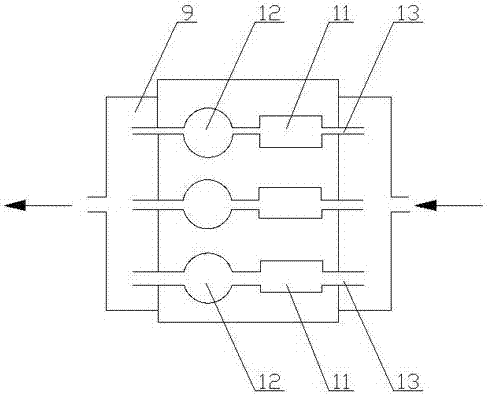
[0046] like figure 2 As shown, compared with Embodiment 1, this embodiment optimizes the liquid flow automatic controller 10, the time relay 11, the solenoid valve 12 and the pipeline 13 form a flow control path, and the liquid flow automatic controller 10 is provided with two parallel connections. The flow control path above.

[0047] In this embodiment, the connection of the pipeline 13 can be controlled by the time relay 11 and the solenoid valve 12, thereby controlling whether the cylinder overflow port 7 or the overflow tank overflow port 8 is conducting.

Embodiment 3

[0049] like figure 2As shown, compared with Embodiment 2, the present embodiment optimizes the liquid flow automatic controller 10, and three flow control passages are arranged in parallel, and the diameters of the pipes 13 of the three flow control passages arranged in parallel are respectively 15 mm, 20 mm and 25mm.

[0050] In this embodiment, the flow rate can be adjusted through three different flow control channels, so that the liquid level can be quickly stabilized.


PUM

PropertyMeasurementUnit
Caliberaaaaaaaaaa
Water permeability coefficientaaaaaaaaaa

Abstract

The invention discloses a determining device and method of a water permeability coefficient of concrete. The device comprises a transparent cylinder, an overflow water tank and a measuring cylinder, wherein scales are engraved on the outer side walls of the transparent cylinder, the overflow water tank and the measuring cylinder, the transparent cylinder is vertically arranged in the overflow water tank, upper and lower ends of the transparent cylinder are open, and a concrete sealing and fixing device is arranged at the lower end opening of the transparent cylinder; a cylinder overflow port is formed in the outer side wall of the upper part of the transparent cylinder, an overflow water tank overflow port is formed in the outer side wall of the overflow water tank, the metering cylinder is arranged below the overflow water tank overflow port, and a rotor flow meter and an automatic liquid flow controller are sequentially mounted at the cylinder overflow port and the overflow water tank overflow port; the automatic liquid flow controller consists of a time relay, a solenoid valve and a pipeline. The device has the benefits as follows: the scales with the division value of mm are engraved on surfaces of the metering cylinder and the overflow water tank of the determining device, reading is convenient and quick, and the condition that the accuracy is affected due to long-term water logging of the scale values can be avoided.

Description

technical field [0001] The invention relates to a measuring device and a method thereof, in particular to a concrete water permeability measuring device and a method thereof. Background technique [0002] With the acceleration of the country's "Belt and Road" construction, large-scale municipal roads, expressways and water conservancy projects are increasing day by day. However, in order to meet the requirements of high strength and durability of concrete, most roads are paved with compactness. Although it brings some convenience to our life, it will have many negative impacts on the ecological environment, such as the lowering of the groundwater level, the urban heat island effect, and the excessive pressure on the urban drainage system. In addition, the dense road surface will cause water accumulation on the road in rainy days, which is not conducive to travel safety. Therefore, the concept of sponge city came into being, and the application of permeable concrete is be...

Claims


Application Information

Patent Timeline
IPC IPC(8): G01N15/08
CPCG01N15/08
Inventor 梁丽敏李世华焦岩马敏超田帅李翔周耀旭王模弼李云明张立志刘旭刚郝国祥刘武刚潘杰曹蓉李锐
Owner 云南建投绿色高性能混凝土股份有限公司
Learn More