
Automatic winding device for electromagnetic valve coil

A solenoid valve coil and automatic winding technology, which is applied in the direction of inductance/transformer/magnet manufacturing, circuits, electrical components, etc., can solve the problems of high coil production cost, low coil winding quality, low production efficiency, etc., and achieve improvement The effect of winding quality, improving winding efficiency, and improving quality

Active Publication Date: 2017-12-01
哈尔滨博信智能装备有限公司
View PDF6 Cites 5 Cited by
  • Summary
  • Abstract
  • Description
  • Claims
  • Application Information

AI Technical Summary

Problems solved by technology

[0007] The purpose of the present invention is to provide an automatic winding device for solenoid valve coils, which can effectively solve the problems of low production efficiency, low coil winding quality and high coil production costs in the prior art solenoid valve coil production equipment. Provides an automatic winding device capable of automatic winding of solenoid valve coils and replaces manual winding of coils; the invention can effectively improve winding efficiency, reduce production costs, and improve winding quality

Method used


Image

  • Automatic winding device for electromagnetic valve coil
  • Automatic winding device for electromagnetic valve coil
  • Automatic winding device for electromagnetic valve coil

Examples


specific Embodiment approach 1

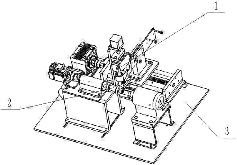
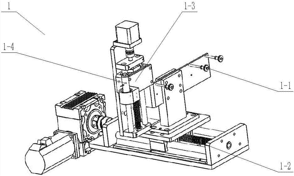
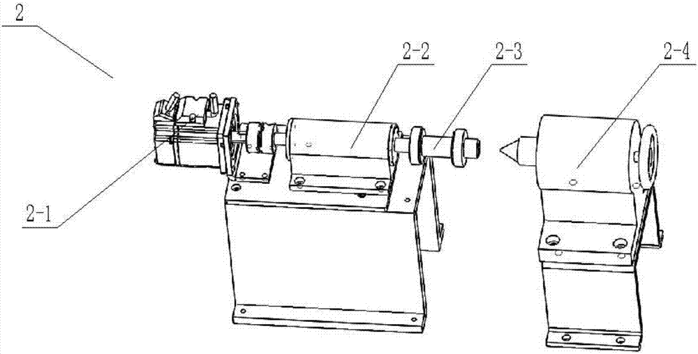
[0034] Such as Figure 1-8 As shown, a solenoid valve coil automatic winding device includes a wire winding mechanism 1, a winding mechanism 2 and a base plate 3, and the winding mechanism 2 and the wire winding mechanism 1 are fixedly connected to both sides of the top of the base plate 3. The wire arranging mechanism 1 is composed of a wire passing wheel mechanism 1-1, a horizontal movement module 1-2, a vertical movement module 1-3 and a needle guide mechanism 1-4, and the wire passing wheel mechanism 1-1 is connected and installed on The upper end of the horizontal movement module 1-2; the vertical movement module 1-3 is connected and installed on the wire passing wheel mechanism 1-1; the horizontal movement module 1-2 is connected and installed on the top of the base plate 3; the The needle guide mechanism 1-4 is connected and installed on the vertical motion module 1-3; the winding mechanism 2 is composed of a servo motor 12-1, a shafting component 2-2, a coil clamp 2-3 ...


PUM


Abstract

The invention relates to an automatic winding device and particularly relates to an automatic winding device for an electromagnetic valve coil. The automatic winding device comprises a wire arrangement mechanism, a winding mechanism and a base plate, wherein the wire arrangement mechanism and the winding mechanism are fixedly connected with two sides of the top end of the base plate; the wire arrangement mechanism comprises a wire passing wheel mechanism, a horizontal motion module, a vertical motion module and a guide pin mechanism; the wire passing wheel mechanism is connected with and arranged at the upper end of the horizontal motion module; the vertical motion module is connected with and arranged on the wire passing wheel mechanism; the horizontal motion module is connected with and arranged at the top end of the base plate; and the guide pin mechanism is connected with and arranged on the vertical motion module. The problems of relatively low production efficiency of the electromagnetic valve coil, poor coil winding quality and high coil production cost in the prior art can be effectively solved. The invention provides an automatic winding device capable of automatically winding the electromagnetic valve coil and replacing hands to wind the coil. The winding efficiency can be improved, the production cost can be reduced and the winding quality can be improved.

Description

technical field [0001] The invention relates to an automatic winding device, in particular to an automatic winding device for a solenoid valve coil. Background technique [0002] The main function of the low-temperature solenoid valve is to control the opening and closing of the low-temperature fluid medium passage, reversing, adjust the flow and pressure, and protect the safety of the system in the pressurized delivery system of the power unit. The solenoid valve coil uses the electromagnetic force generated in the electromagnetic component circuit to attract the valve core, so as to achieve the function of reversing or switching. Therefore, the quality of the coil has a great influence on the reliability of the solenoid valve. In the production process of solenoid valve coils, coil winding is a very critical process. [0003] At present, the winding of the coil of the low-temperature solenoid valve mainly adopts the manual winding method, manually installing the empty coi...

Claims


Application Information

Patent Timeline
Patent Type & Authority Applications(China)
IPC IPC(8): H01F41/066H01F41/082H01F41/077
CPCH01F41/066H01F41/077H01F41/082
Inventor 周亮金光远陈剑箫郭豪王娜君
Owner 哈尔滨博信智能装备有限公司
Learn More