Heddle preferably for processing strip-like warp material and method for producing a heddle

A technology for processing belts and warp yarns, applied in textiles, papermaking, weaving, looms, etc., can solve the problems of complicated and expensive manufacturing of weaving heddles, and achieve the effect of eliminating friction

Active Publication Date: 2017-12-01
GROZ BECKERT KG
View PDF8 Cites 0 Cited by
  • Summary
  • Abstract
  • Description
  • Claims
  • Application Information

AI Technical Summary

Problems solved by technology

Since the heddle has a constant width over its entire length, it also has the disadvantage that during the weaving operation the warp threads relatively often rub

Method used


Image

  • Heddle preferably for processing strip-like warp material and method for producing a heddle
  • Heddle preferably for processing strip-like warp material and method for producing a heddle
  • Heddle preferably for processing strip-like warp material and method for producing a heddle

Examples


Embodiment Construction

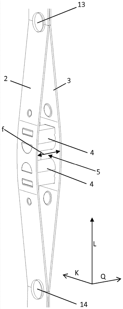
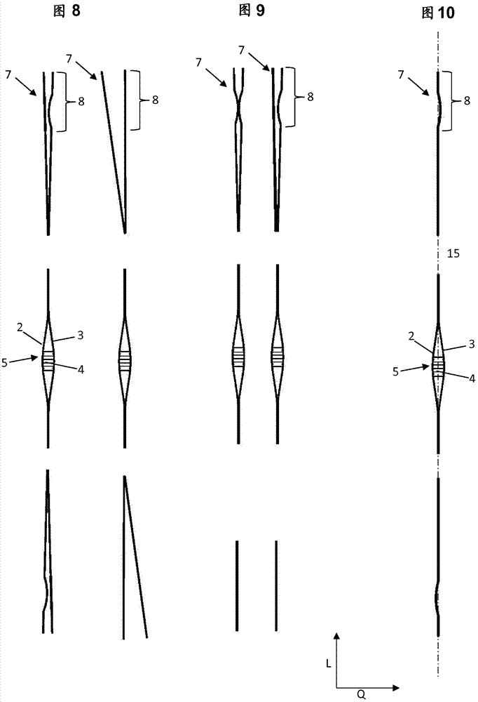
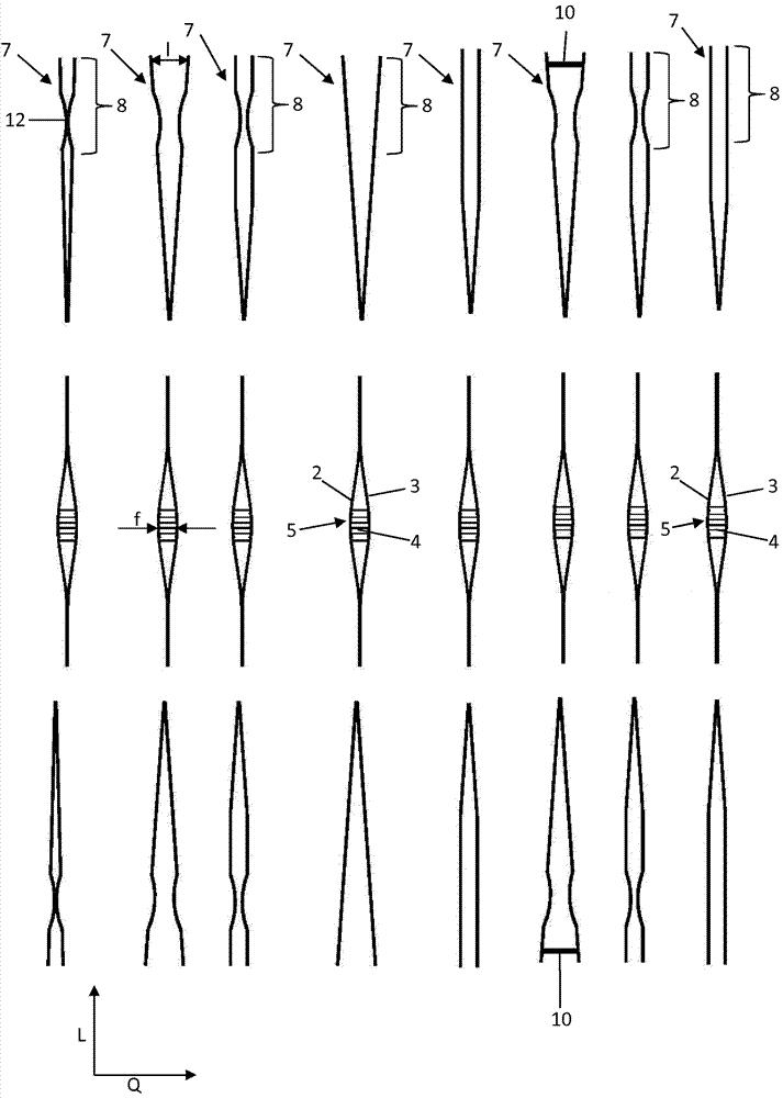
[0052] as by figure 1 As can be seen, the weaving heddle comprises a first strip 2, a second strip 3 and two structural elements 4, by means of which the two strips 2, 3 are aligned in the transverse direction Q in the region of the thread guide eye 5. on separated. Adjoining the eyelet area is a shank area 6 on both sides in the longitudinal direction L. The two strips 2 , 3 rest against each other over a wide distance in the shaft area. At the end of the shank region 6 there is correspondingly an end eye 7 . In the area of ​​the end eyelets 8 (area of ​​the end eyelets 7 ), the two strips are bent over one another in the transverse direction (up to the respective heddle end 9 ) by a length l which is greater than the width of the guide eyelet 5 f (in the transverse direction Q). Additionally, spacer elements (10; see Figure 7 ) is introduced into the end eyelet area 8 . The size of the length l is selected so that when the heddles are mounted on the support rails of t...


PUM


Abstract

The invention relates to a heddle comprising two strips (2, 3), which form the heddle shaft (6), at least one component (4) for delimiting the thread eye (5), and at least two end loops (7). The at least two strips (2, 3) are spaced in the transverse direction (Q) in the region of the thread eye (5), and the at least one component (4) is arranged in the region of the thread eye (5) between the at least two strips (2, 3). The at least two strips (2, 3) are adjacent to each other at least in sections in front and behind the thread eye (5) in the longitudinal direction (L). At least one point in the region of at least one of the at least two end loops (7) at least one of the at least two strips (2, 3) runs in the transverse direction to a side at a distance from a central axis (15) of the heddle (1) and at a further point in the region of at least one of the at least two end loops (7) at least one of the at least two strips (2, 3) runs to the other side at a distance from the central axis (15).

Description

Background technique [0001] Healds are known from the prior art, the shaft of which is produced from two strips. [0002] Thus, documents EP 2 730 688 A1 and EP 2 730 687 A1 show healds for processing preferably tape-like warp material, the stems of which are formed by two strips in each case. End eyelets are formed in the region of the two ends of the shaft. The two strips are separated by at least one structural element in the central region of the shank, whereby a thread guide eye is formed. The two strips rest against each other in the remaining area of ​​the shaft. The healds can be produced relatively cost-effectively, but have the disadvantage that in the position of use, that is, when the healds are inserted into the support rail of the weaving machine by means of the end eyelets, the healds are The normal gap between the end eyelets of the heald can be rotated around its longitudinal axis over a larger angular range, so that it can be clearly tilted. During the we...

Claims


Application Information

Patent Timeline
IPC IPC(8): D03C9/02D03D41/00
CPCD03C9/02D03D41/008
Inventor C.格特R.格罗斯曼
Owner GROZ BECKERT KG
Why Eureka
Try Eureka