Valve for controlling a fluid flow

A technology of fluid communication and fluid inlet, which is applied in the field of gas injection valves and can solve the problems of complex manufacturing and short life

Active Publication Date: 2017-12-01
오이겐자이츠아게
View PDF6 Cites 3 Cited by
  • Summary
  • Abstract
  • Description
  • Claims
  • Application Information

AI Technical Summary

Problems solved by technology

However, such flexible membranes or dynamic seals have the disadvantage that on the one han...

Method used


Image

  • Valve for controlling a fluid flow
  • Valve for controlling a fluid flow
  • Valve for controlling a fluid flow

Examples


Embodiment Construction

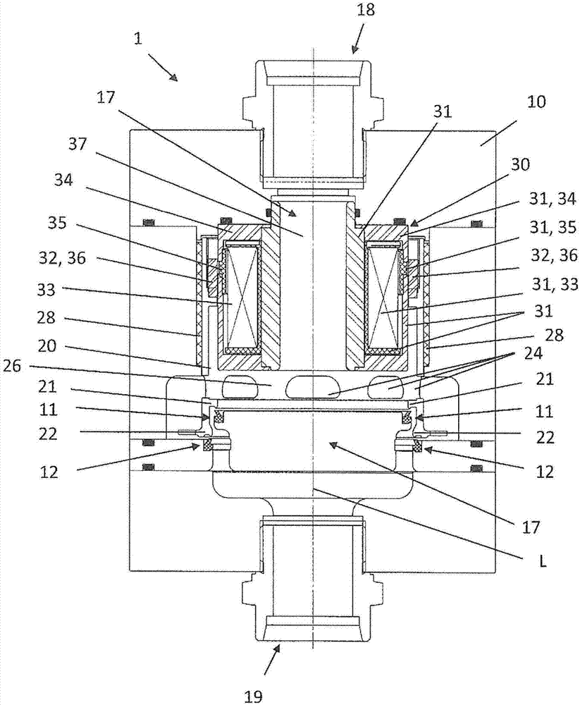
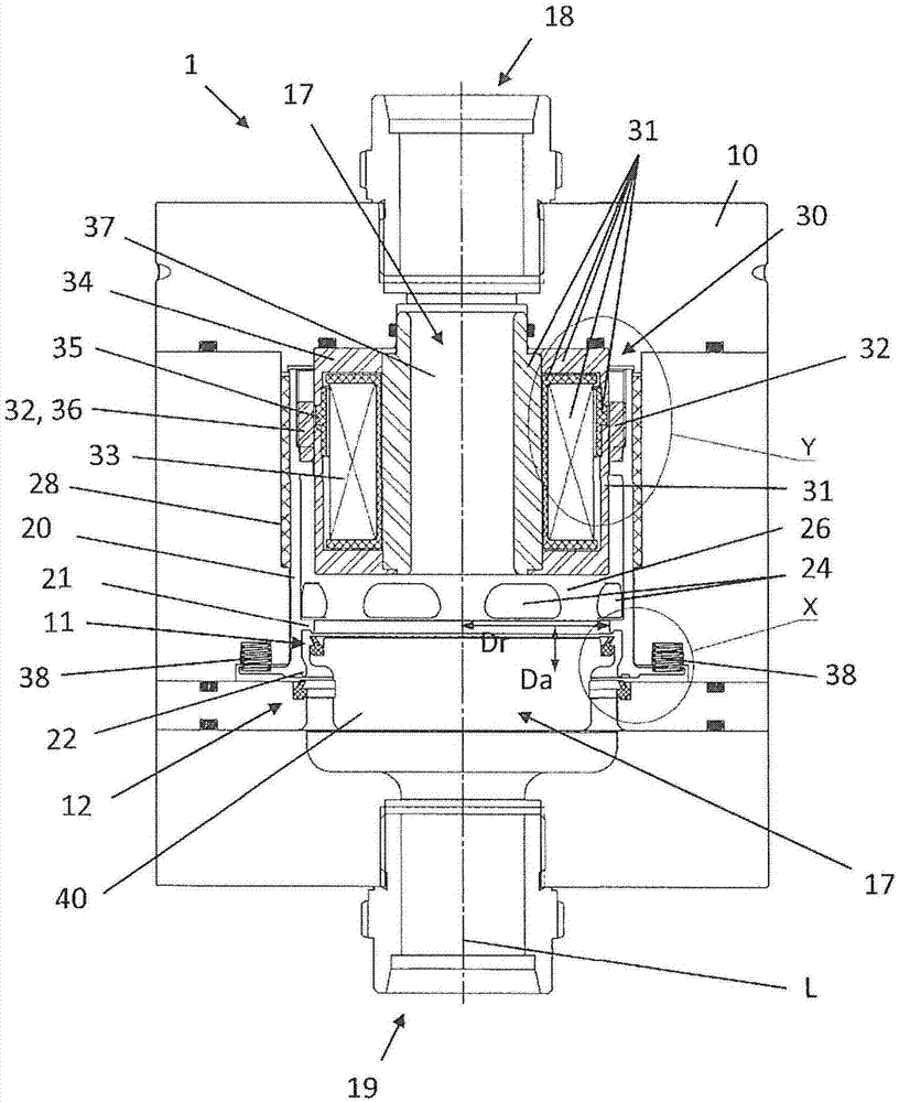
[0045] Figures 1 to 4 One possible embodiment of the valve 1 according to the invention is shown. The valve 1 has a valve housing 10 in which a sleeve section 23 and further The substantially hollow-cylindrical closure element 20 of the sleeve section 26 is arranged displaceably along the sleeve longitudinal axis L on a slide bearing 28 . An actuator 30 is used to move the closure element 20 between the open position and the closed position of the valve 1, which actuator moves the closure element 20 into the closed position against the force of a plurality of return springs 38 distributed around the circumference. middle. Figures 1 to 4 Valve 1 is shown in an open position.

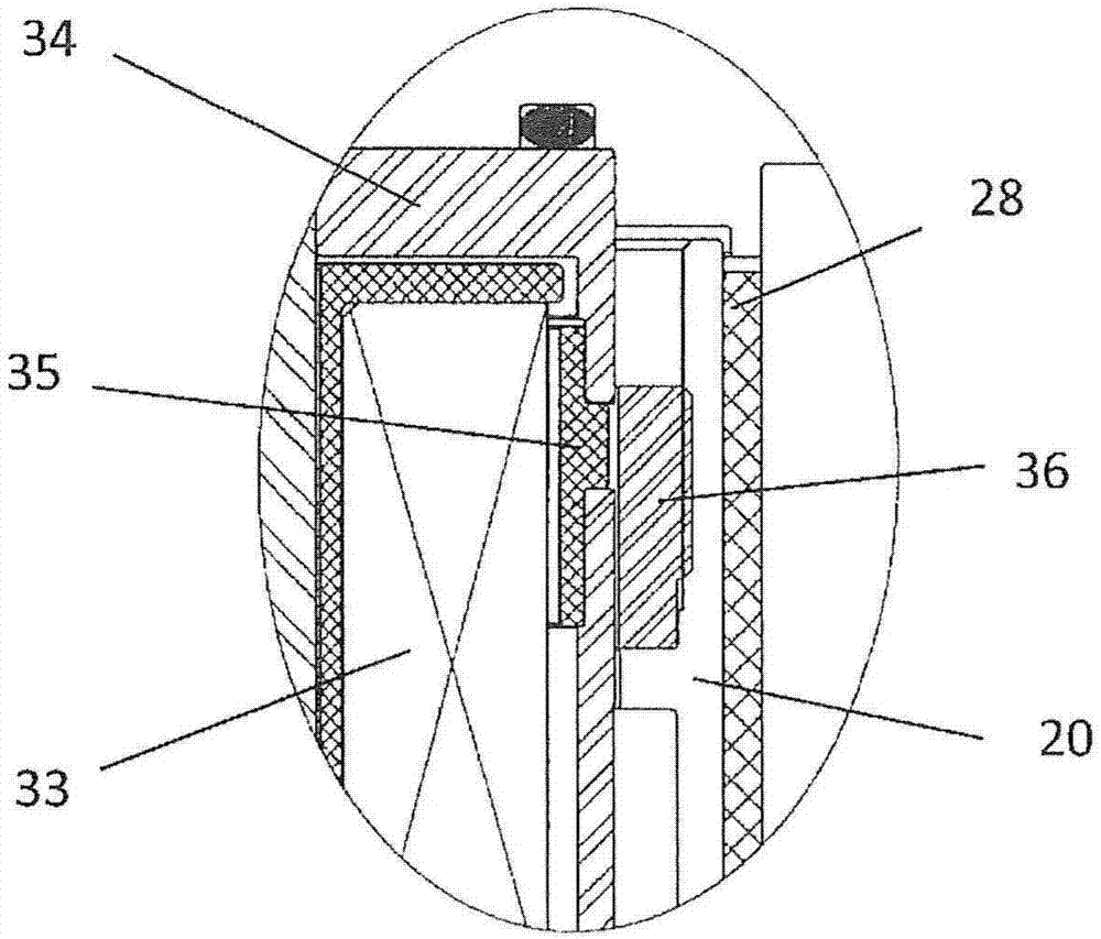
[0046] In the present exemplary embodiment, the actuator 30 is designed as an electromagnetic reluctance actuator having a magnetic field coil 33 , a magnet conductor 34 with an air gap 35 and a magnet armature 36 . In this case, the field coil 33 and the magnet conductor 34 with the air gap 35 are ...


PUM


Abstract

The invention relates to a valve (1) having a valve housing (10) in which, for the purpose of opening and closing a fluid connection between a fluid inlet (18) and a fluid outlet (19) of the valve housing (10), a closure element (20) having at least one sleeve section (23) can be moved along its sleeve longitudinal axis (L) by means of an actuator (30), wherein the actuator (30) has parts (31, 32) that are respectively stationary and movable with respect to the valve housing (10) and at least the movable parts (32) of the actuator (30) and the closure element (20) are arranged entirely within a fluid space (17), enclosed by the valve housing (10), between the fluid inlet (18) and the fluid outlet (19), and wherein the valve (1) has at least one double-seal seat which has on the sleeve section (23) a first and a second seal device (21, 22), spaced apart therefrom along the sleeve longitudinal axis (L), and on the valve housing (10) a first and a second counter-seal device (11, 12), accordingly spaced apart equally, wherein in order to close the fluid connection the first seal device (21) is in sealing contact with the first counter-seal device (11) along a first closed seating line and the second seal device (22) is in sealing contact with the second counter-seal device (12) along a second closed seating line, and wherein, with regard to the at least one double-seal seat, the ratio between a first area enclosed by the first sealing line in projection along the sleeve longitudinal axis (L) and a second area enclosed by the second sealing line in projection along the sleeve longitudinal axis (L) is between 6/10 and 10/6.

Description

technical field [0001] The invention relates to a valve for controlling a fluid flow, in particular a gas injection valve, which is at least partially, preferably completely, pressure-balanced. Background technique [0002] Such a valve can be used, for example, as a gas injection valve for controlling the injection of fuel gas at a first pressure into an air flow at a second, lower pressure which is further conveyed together with the injected fuel gas to the combustion chamber of the internal combustion engine. In order to be able to achieve fast and precise control of the gas flow, such valves must be able to switch between a closed position and an open position very quickly. This can be achieved on the one hand by a rapidly switching drive or actuator. On the other hand, it is possible to design the valve in such a way that the drive must exert as little force as possible to switch the valve closure back and forth against the pressure acting on it. For this purpose, so...

Claims


Application Information

Patent Timeline
IPC IPC(8): F02M21/02F16K1/44F02M51/06F02M61/18F16K25/00F16K31/06
CPCF02M21/0266F16K31/0655F02M21/0254F16K31/0651F02M2200/08F02M2200/16Y02E20/14Y02T10/30F02M51/0689F16K31/0693F16K31/082
Inventor M·拉姆斯伯格尔G·莫拉维厄兹
Owner 오이겐자이츠아게
Why Eureka
Try Eureka