Clamp structure used for center hole positioning and clamping

A hole positioning and clamping technology, which is applied in the direction of manufacturing tools and workpiece clamping devices, can solve the problems of cumbersome clamping steps, axial positioning errors, and low positioning accuracy, so as to reduce the weight of the fixture, reduce the height of the fixture, and improve Effect of Fixture Accuracy

Active Publication Date: 2017-12-05
江苏瑞尔隆盛叶轮科技有限公司
View PDF6 Cites 3 Cited by
  • Summary
  • Abstract
  • Description
  • Claims
  • Application Information

AI Technical Summary

Problems solved by technology

For the hole diameter above 8mm, the oil pressure can be used to position and lock the part inside the pin. The disadvantage of this mechanism is that the cost of the fixture is high, and the equipment itself must be equipped with an oil circuit; it will exert pressure on the inner hole of the part, Cause local stress deformation and indentation, the force of the fixed parts of the fixture is a vector in the circumferential direction, which will cause axial positioning errors
For the positioning aperture below 4-8mm, screws are generally used for locking at present, and parts are inevitably scratched, positioning accuracy is not high, the clamping steps are cumbersome, and the screws are easy to break / slip, etc.

Method used


Image

  • Clamp structure used for center hole positioning and clamping
  • Clamp structure used for center hole positioning and clamping
  • Clamp structure used for center hole positioning and clamping

Examples


Embodiment Construction

[0028] The specific embodiment of the present invention is further described below in conjunction with accompanying drawing:

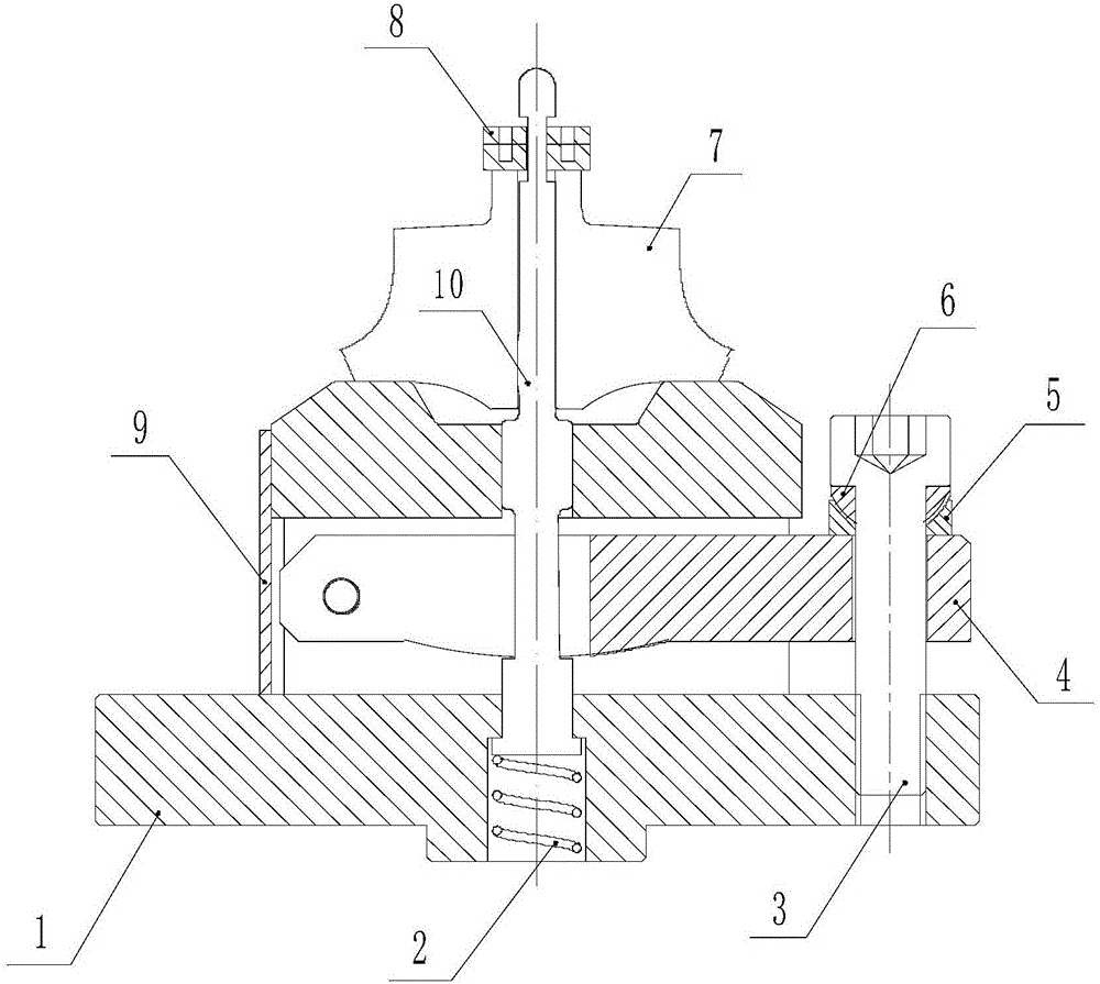
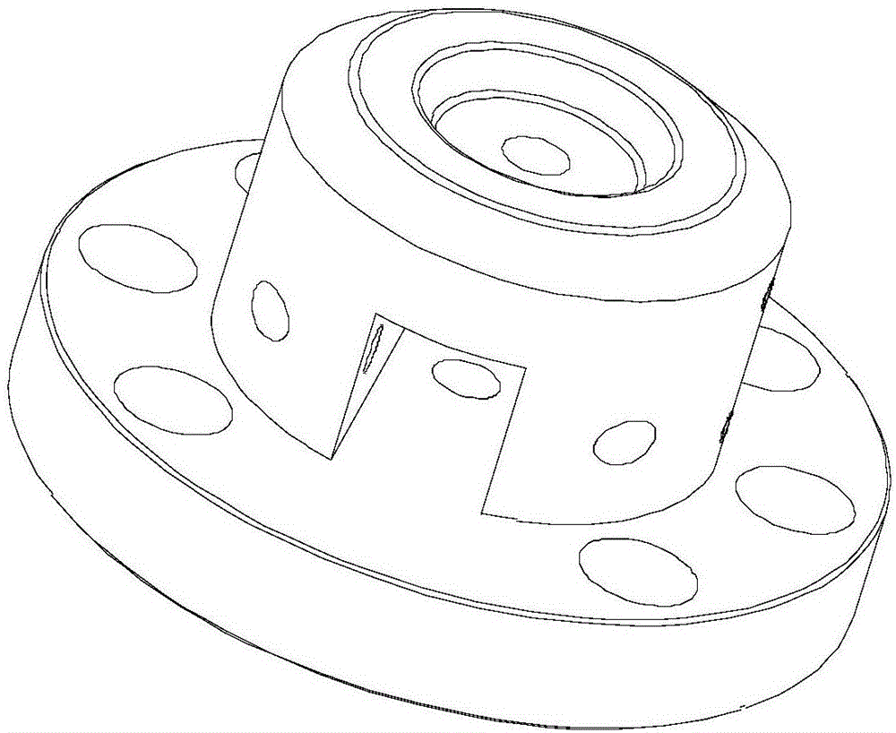
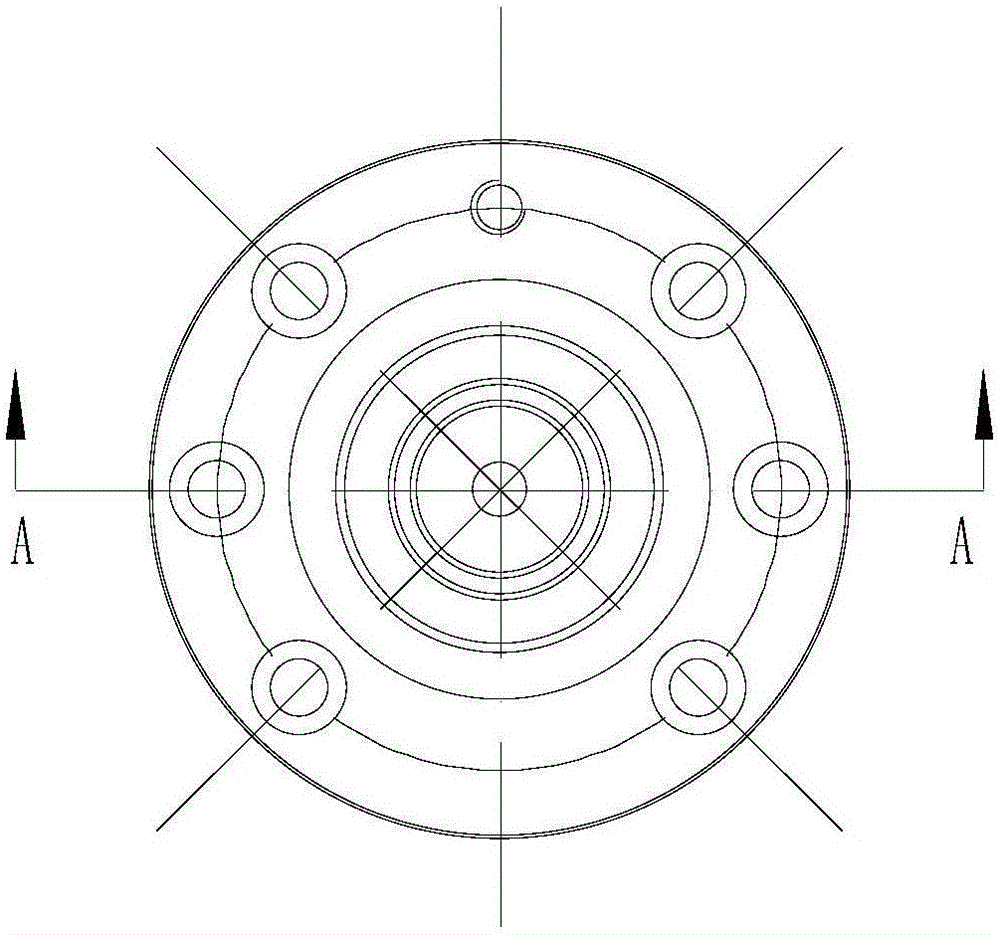
[0029] A fixture structure for center hole positioning and clamping, which includes a base 1, a spring 2, a screw 3, a pressure rod 4, a lower circular washer 5, an upper circular washer 6, a pressure head 8, a tin plate 9 and a positioning pin 10. The base 1 is a flange structure, the bottom of the positioning pin 10 is installed in the center hole of the base 1, the spring 2 is installed in the center hole of the base 1 and the top surface of the spring 2 On the bottom surface of the positioning pin 10, the pressure rod 4 is installed in the square groove of the base 1 through the rotating shaft, the lower circular washer 5 is sleeved on the screw 3 and the bottom surface of the lower circular washer 5 is supported on the pressure rod 4, the upper circular washer 6 is installed in the arc groove of the lower circular washer 5 and the upper circular w...


PUM


Abstract

The invention discloses a clamp structure used for center hole positioning and clamping. A base is in a form of a flange plate structure, the bottom of a positioning pin is installed in a center hole in the base, a spring is installed in the center hole in the base, and the top face of the spring is pressed against the bottom face of the positioning pin. A press rod is installed in a square groove in the base through a rotary shaft, a screw is sleeved with a lower circular gasket, and the bottom face of the lower circular gasket is pressed against the top face of the press rod. An upper circular gasket is installed in an arc-shaped groove in the lower circular gasket, the screw is sleeved with the upper circular gasket, the tail portion of the screw is installed in a threaded hole in the base, and the screw passes through a through hole in the press rod. A part is installed on the top face of the base, the positioning pin is sleeved with the part and a pressure head, the bottom face of the pressure head is pressed against the top face of the part, and a galvanized iron sheet is fixedly installed on the outer cylindrical surface of the base through a bolt. The clamp structure can be suitable for any machining devices, and no machining region space can be occupied; the clamp structure has the advantages of being low in manufacturing cost, convenient in clamping, high in positioning and clamping precision, long in service life and the like.

Description

technical field [0001] The invention belongs to the technical field of clamps, and in particular relates to a clamp structure for center hole positioning and clamping. Background technique [0002] Many precision parts are positioned by holes, especially some parts with high precision and many processing procedures need to be positioned by holes. For the hole diameter above 8mm, the oil pressure can be used to position and lock the part inside the pin. The disadvantage of this mechanism is that the cost of the fixture is high, and the equipment itself must be equipped with an oil circuit; it will exert pressure on the inner hole of the part, Cause local stress deformation and indentation, the force of the fixed parts of the fixture is a vector in the circumferential direction, which will cause axial positioning errors. For the positioning aperture below 4-8mm, screws are generally used for locking at present, which inevitably leads to scratches on parts, low positioning acc...

Claims


Application Information

Patent Timeline
Patent Type & Authority Applications(China)
IPC IPC(8): B25B11/00
CPCB25B11/00
Inventor 韩海龙洪友谊
Owner 江苏瑞尔隆盛叶轮科技有限公司
Why Eureka
Try Eureka