Hot melt adhesive cutter body installation structure for towel cloth compounding

An installation structure and hot-melt adhesive technology, applied in lamination devices, layered products, lamination, etc., can solve the problems of not being able to apply glue, inconvenient movement, and affecting the movement of the knife body, so as to achieve convenient movement and rotation, and guarantee The effect of gluing quality

Pending Publication Date: 2017-12-05
JIANGSU KUNTAI MACHINERY
View PDF6 Cites 2 Cited by
  • Summary
  • Abstract
  • Description
  • Claims
  • Application Information

AI Technical Summary

Problems solved by technology

At the same time, during the gluing process, the dander and small particles on the surface of the product will stick to the surface of the rubber roller, and the scraper is not easy to scrape it off. If it is not cleaned for a long time, the gluing quality of the product will be affected. Especially products such as terry cloth and plush cloth need to be cleaned frequently. When cleaning the surface of the upper rubber roller, the knife body and scraper need to be removed by the moving device. During the movement of the knife body, due to the oil inlet pipe Both the oil inlet pipe and the oil outlet pipe are arranged on one side of the scraper, which is inconvenient to move. The existing installation method of the oil inlet pipe and the oil outlet pipe affects the movement of the knife body, resulting in the existing hot melt adhesive gluing device cannot be used for products such as terry cloth and plush cloth. well glued

Method used


Image

  • Hot melt adhesive cutter body installation structure for towel cloth compounding
  • Hot melt adhesive cutter body installation structure for towel cloth compounding
  • Hot melt adhesive cutter body installation structure for towel cloth compounding

Examples


Embodiment Construction

[0010] The specific content of the present invention will be described in detail below in conjunction with the accompanying drawings and specific embodiments.

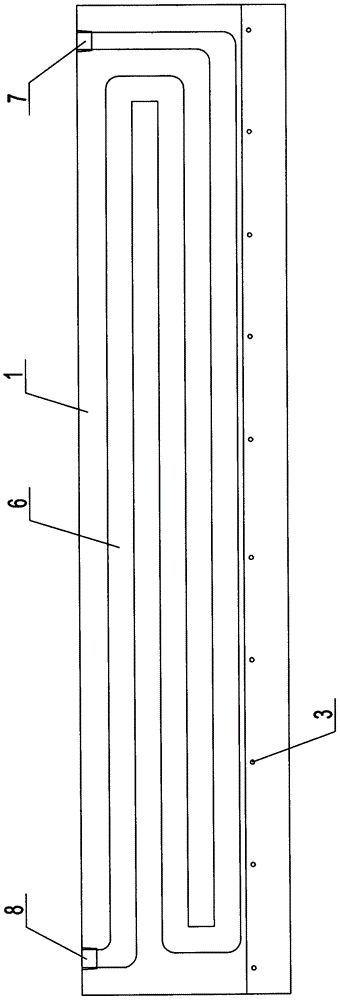
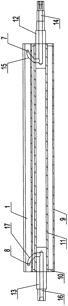
[0011] Such as figure 1 , figure 2 , image 3 As shown, the installation structure of the hot-melt adhesive knife body used for terry cloth compounding includes: a knife body 1 and an upper rubber roller 2, a number of scraper mounting holes 3 are evenly arranged on the knife body 1, and the scraper 4 passes through bolts, scraper blades, etc. The pressure plate 5 and the scraper installation hole 3 are fixed on the cutter body 1, and a labyrinth-type heat-conducting oil heating chamber 6 is arranged inside the cutter body 1, and a labyrinth-type heat-conducting oil heating chamber 6 is arranged on one side of the cutter body 1 The oil inlet 7 connected at one end is provided with the oil outlet 8 connected with the other end of the labyrinth heat transfer oil heating chamber 6 on the other side of the cutter body 1...


PUM


Abstract

The invention discloses a hot melt adhesive cutter body installation structure having a characteristic of convenient cutter body moving and used for towel cloth compounding. The hot melt adhesive cutter body installation structure comprises a cutter body and a glue adding roller, wherein the cutter body is uniformly provided with a plurality of scraping cutter installation holes, a scraping cutter is fixed on the cutter body through a bolt, a scraping cutter pressing plate and the scraping cutter installation holes, a labyrinth type heat conducting oil heating chamber is arranged in the cutter body, one side of the cutter body is provided with an oil inlet communicated to one end of the labyrinth type heat conducting oil heating chamber, the other side of the cutter body is provided with an oil outlet communicated to the other end of the labyrinth type heat conducting oil heating chamber, the cutter body is supported on a square pipe, a hollow shaft is arranged inside the square pipe through a plurality of supporting rods, both ends of the hollow shaft are respectively connected to an oil inlet connection shaft and an oil outlet connection shaft, and an oil inlet connection channel is arranged inside the oil inlet connection shaft.

Description

technical field [0001] The invention relates to a gluing device for a compound machine, in particular to a hot-melt glue cutter body installation structure for terry cloth compounding. Background technique [0002] In the process of compounding products such as thin cloth, film, terry cloth, plush cloth, etc., hot melt adhesive glue device will be used. scrape. In order to improve the quality of gluing, the cutter body of the existing gluing device is provided with a heat conduction oil heating chamber, and the oil inlet and oil outlet at both ends of the heat conduction oil heating chamber are respectively connected with the oil inlet pipe and the oil outlet pipe arranged on the side close to the scraper. , so that the surface of the cutter body is heated evenly to ensure the gluing effect. At the same time, during the gluing process, the dander and small particles on the surface of the product will stick to the surface of the rubber roller, and the scraper is not easy to...

Claims


Application Information

Patent Timeline
Patent Type & Authority Applications(China)
IPC IPC(8): B32B37/12B32B37/06B32B37/00
CPCB32B37/0046B32B37/06B32B37/12
Inventor 陆顺杰王忠孙祥俊柏晋敏
Owner JIANGSU KUNTAI MACHINERY
Why Eureka
Try Eureka