Electronic hydraulic door closer

An electronically controlled hydraulic and door closer technology, which is applied in door/window accessories, switches with brake devices, buildings, etc., can solve the unreasonable setting of the external mechanism of the door closer, and the opening and closing of the door closer Unsmooth, large door closer structure and other problems, to achieve the effect of reliable locking limit, compact structure, and small footprint

Inactive Publication Date: 2017-12-05
LISHUI SHENFEI LIYI SECURITY PRODS
View PDF5 Cites 4 Cited by
  • Summary
  • Abstract
  • Description
  • Claims
  • Application Information

AI Technical Summary

Problems solved by technology

[0002] The existing technology lacks an electronically controlled hydraulic door closer. The external mechanism of the door closer is unreasonably set, resulting in the door closer not being able to open and close smoothly, and prone to jamming. Therefore, it is urgent to develop a new type of external mechanism, optimize the structure of the door closer
Conventional solenoid valves cannot meet the special needs of door closers, and it is necessary to set up interfaces on the door closers to install solenoid valves. Because external ports need to be reserved, the structure of the door closers is relatively large, and the volume cannot be further reduced. Therefore, according to the closing To meet the actual needs of the door closer, develop a special door stop solenoid valve that can be quickly connected and replaced with the door closer, reduce the number and volume of the door closer components, improve the compactness of the overall door closer, and improve the convenience of maintenance sex

Method used


Image

  • Electronic hydraulic door closer
  • Electronic hydraulic door closer
  • Electronic hydraulic door closer

Examples


Embodiment 1

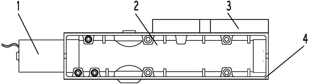
[0049] like figure 1 As shown, the electronically controlled hydraulic door closer includes an external mechanism 1, a door stop solenoid valve 2, a rocker arm 3, and a mounting plate 4;

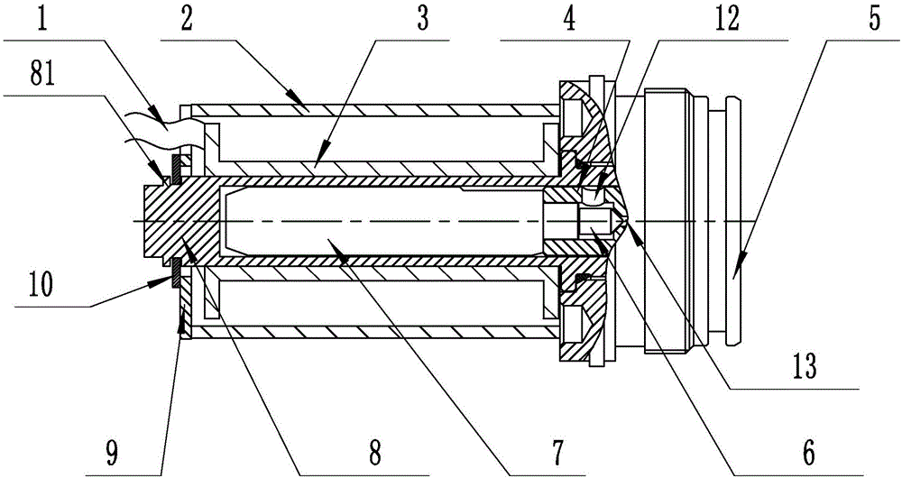
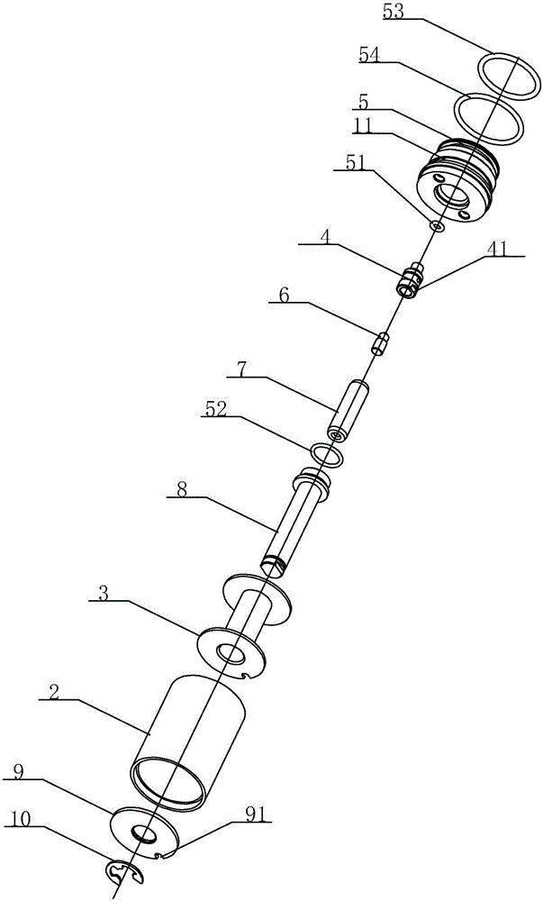
[0050] like Figure 4-8 As shown, the external mechanism includes a door stop plate 1, a mounting plate 2, a door stop plate limiter 3; a door stop plate 1, which is slidably arranged on the top of the mounting plate 2; a mounting plate 2, which is provided with a guide 4 and a coil Mounting bracket 5, door stop plate 1 is inserted in the bottom groove of guide member 4; Door stop plate limiter 3, it is reversibly installed on the coil mounting bracket 5, is provided with electromagnet sucker 6 on it, and coil mounting bracket is provided with Electromagnetic coil 7 is arranged (to provide magnetic force, to hold the electromagnet chuck 6). The limit block 11 cooperates with the stop pin 8 arranged on the electro-hydraulic door closer and is used for intermittent contact limit. The left e...


PUM


Abstract

The invention discloses an electronic hydraulic door closer which comprises an external mechanism, a door stop solenoid valve and a rocker arm. The external mechanism comprises a stop plate, a mount plate and a stop plate limiter. The rocker arm of the door closer comprises a rocker arm body and a regulating arm connected in sequence; a rotation shaft and the stop plate with limit angle capable of being regulated rotationally are arranged on the rocker arm; the stop plate is provided with a limit notch, the limit notch is meshed with a steel ball in the rocker arm body, and the steel ball is abutted by a spring. As an oil circuit and an end cap of the door closer are connected into a whole, the integral structural design of the door closer is much more reasonable and compacter, the structure size of the door closer is reduced, maintenance and changing of the door closer are facilitated, and the door closer has higher specificity.

Description

technical field [0001] The invention relates to the technical field of door closers, in particular to an electronically controlled hydraulic door closer. Background technique [0002] The existing technology lacks an electronically controlled hydraulic door closer. The external mechanism of the door closer is unreasonably set, resulting in the door closer not being able to open and close smoothly, and prone to jamming. Therefore, it is urgent to develop a new type of external mechanism to optimize the structure of the door closer. Conventional solenoid valves cannot meet the special needs of door closers, and it is necessary to set up interfaces on the door closers to install solenoid valves. Because external ports need to be reserved, the structure of the door closers is relatively large, and the volume cannot be further reduced. Therefore, according to the closing To meet the actual needs of the door closer, develop a special door stop solenoid valve that can be quickly c...

Claims


Application Information

Patent Timeline
Patent Type & Authority Applications(China)
IPC IPC(8): E05F3/12E05F3/22
CPCE05F3/12E05F3/22
Inventor 杨金峰任偎刘朝忠吴振波孙冬冬
Owner LISHUI SHENFEI LIYI SECURITY PRODS
Why Eureka
Try Eureka