
Shears-fork type spiral lifting platform

A technology of screw lift and screw lift, applied in the field of scissor screw lift platform, can solve the problems of smaller lifting weight, more maintenance times, extended construction delivery period, etc., to improve stability and safety, compact space structure , the effect of solving the space size

Inactive Publication Date: 2017-12-08
WUHU C&K AUTOMATION TECH CO LTD
View PDF6 Cites 12 Cited by
  • Summary
  • Abstract
  • Description
  • Claims
  • Application Information

AI Technical Summary

Problems solved by technology

[0002] In the field of lifting equipment technology, the common driving methods include hydraulic pressure, air pressure, screw, etc., which realize the lifting function. However, during the rising process of these traditional lifting equipment, the lifting weight will gradually decrease as the height increases. Moreover, the height of the body becomes higher with the increase of the lifting height, which has great limitations.
It is impossible to find a lift that can meet such requirements in an environment where it is installed in a specific narrow space and the height of the body cannot be too high. Usually, the height can be raised, so the body of the lift must be correspondingly higher to realize its function, and it must drive the load. type objects, the lift body must be quite large and the lifting frame must be reinforced to meet the requirements. Some lifting systems have to dig deeper pits to put in large-volume lifts, which increases construction difficulty and prolongs construction delivery. The method is that oil leakage from the sealing part will start after a long time, which will bring more maintenance times and maintenance troubles; the current situation of lack of precision in the automatic control of lifting, the lifting weight and lifting speed of the screw type lifting equipment are obvious. Falling, but also rising, how high the height of the body needs to rise and fix the shortcomings
[0003] Therefore, the existing lifting equipment can no longer meet the needs of people, and there is an urgent need for a new lifting equipment.

Method used


Image

  • Shears-fork type spiral lifting platform
  • Shears-fork type spiral lifting platform
  • Shears-fork type spiral lifting platform

Examples


Embodiment 1

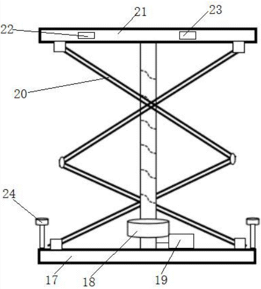
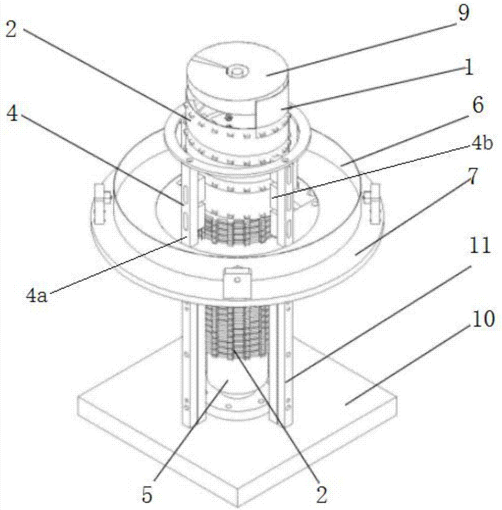
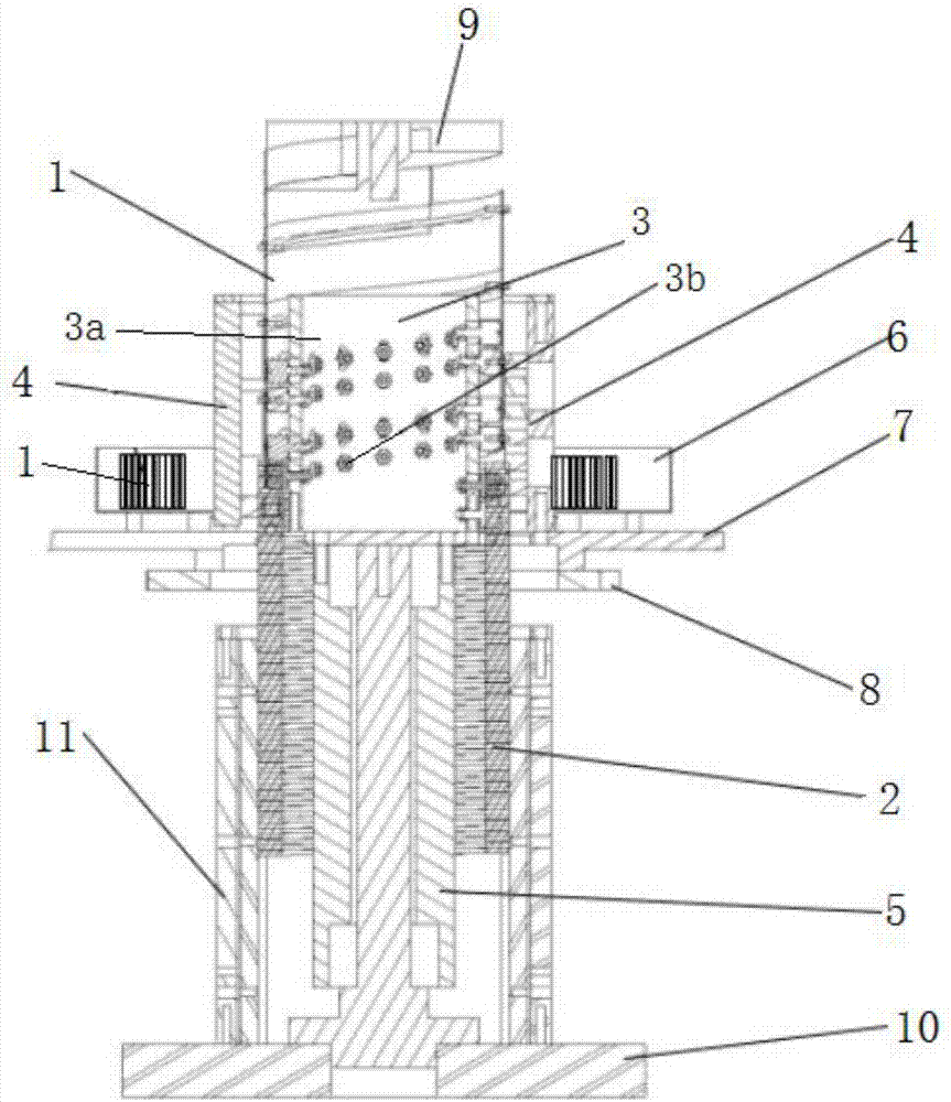
[0042] Such as Figure 1 to Figure 7 As shown, the screw jack 18 includes a fixed base, a platform that rotates around the fixed base, a storage box 6 installed on the platform, a spring flat belt 1 stored in the storage box 6, installed in the fixed base and Cooperate with the spring flat belt 1 to form the toothed spring bar 2 of the spiral cylinder, the belt track lifting mechanism installed on the platform for binding the toothed spring bar 2 to lift or shrink the movement 3, used to make the spring flat belt 1 and the tooth The track guide frame 4 that type spring bar 2 interlocks. The driving device 19 drives the platform to rotate, and then drives the belt track lifting mechanism 3 to rotate, and the belt track lifting mechanism 3 makes the toothed spring bar 2 rise and fall under the guidance of the belt track lifting mechanism 3, and synchronously pulls the spring flat belt 1 spiral Climbing, under the pushing effect of the rail guide frame 4, the spring flat belt 1 ...

Embodiment 2

[0059] Such as Figure 9 to Figure 12 As shown, the screw jack 18 includes a fixed base, a platform that rotates around the fixed base, a storage box 6 installed on the platform, a spring flat belt 1 stored in the storage box 6, installed in the fixed base and Cooperate with the spring flat belt 1 to form the toothed spring bar 2 of the spiral cylinder, the belt track lifting mechanism installed on the platform for binding the toothed spring bar 2 to lift or shrink the movement 3, used to make the spring flat belt 1 and the tooth The track guide frame 4 that type spring bar 2 interlocks. The driving device 19 drives the platform to rotate, and then drives the belt track lifting mechanism 3 to rotate, and the belt track lifting mechanism 3 makes the toothed spring bar 2 rise and fall under the guidance of the belt track lifting mechanism 3, and synchronously pulls the spring flat belt 1 spiral Climbing, under the pushing effect of the rail guide frame 4, the spring flat belt 1...


PUM


Abstract

The invention relates to a shears-fork type spiral lifting platform. The shears-fork type spiral lifting platform comprises an objective table, a spiral lifting machine, a driving device and a controller, wherein the spiral lifting machine is installed on the ground and is used for supporting the objective table, the driving device is used for driving the spiral lifting machine to move, the controller is used for controlling the driving device to operate, and a shears-fork type telescopic bracket which is fixed to the ground and is used for assisting to support the objective table is installed on the objective table. The shears-fork type spiral lifting platform has the advantage of clever structural design, a spiral lifting cylinder is formed in a way that a spring flat belt is engaged with a toothed spring bar, so that the objective table is driven to lift up and down, and auxiliary support to the objective table is realized by utilizing the shears-fork type telescopic bracket during lifting, so that the overall stability and safety are increased; the stage lifting motion is realized in a spiral lifting mode, the space structure is compact, the technical problem of large space size of a traditional lifting mechanism is solved, and the lifting force cannot be suddenly reduced along with the increase of the lifting height, so that the stability and the safety are high.

Description

technical field [0001] The invention relates to the technical field of lifting equipment, in particular to a scissor-type spiral lifting platform. Background technique [0002] In the field of lifting equipment technology, the common driving methods include hydraulic pressure, air pressure, screw, etc., which realize the lifting function. However, during the rising process of these traditional lifting equipment, the lifting weight will gradually decrease as the height increases. Moreover, the height of the body becomes higher with the increase of the lifting height, which has great limitations. It is impossible to find a lift that can meet such requirements in an environment where it is installed in a specific narrow space and the height of the body cannot be too high. Usually, the height can be raised, so the body of the lift must be correspondingly higher to realize its function, and it must drive the load. type objects, the lift body must be quite large and the lifting f...

Claims


Application Information

Patent Timeline
Patent Type & Authority Applications(China)
IPC IPC(8): B66F7/06B66F7/14
CPCB66F7/065B66F7/0666B66F7/14
Inventor 金虎杰
Owner WUHU C&K AUTOMATION TECH CO LTD
Learn More