
Slider angle lock and display

A technology of display screen and slider, applied in the direction of thin plate connection, instruments, connecting components, etc., can solve the problems of low universality, inability to meet the requirements for splicing of various inclination angles, and limited product application occasions.

Active Publication Date: 2018-07-27
SHENZHEN EASTAR ELECTRONICS
View PDF7 Cites 0 Cited by
  • Summary
  • Abstract
  • Description
  • Claims
  • Application Information

AI Technical Summary

Problems solved by technology

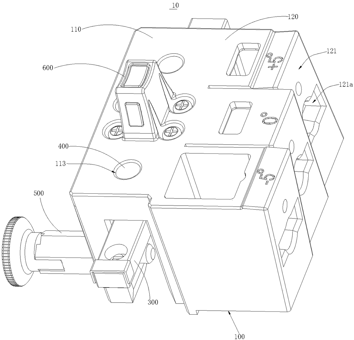
[0003] In the prior art, there are the following problems in the arc splicing of the LED display screen: the side edge of the main cabinet of the LED display is processed with an inclined splicing surface. When the two main cabinets are spliced, the two main cabinets will An included angle is formed to achieve the effect of radian splicing, that is, the main box of the LED display is directly made into a "corner-cutting box" at a certain angle, and the inclination angle of the splicing surface is processed according to the actual situation, and multiple boxes are spliced ​​into a large After the screen, a curved screen can be formed. After the main box of the LED display is made into a "corner-cut box", the display can only be spliced ​​into a large screen with a curvature, which limits the application of the product, that is, it cannot meet the requirements for multiple applications. The splicing requirements of different inclined angles are low in universality

Method used


Image

  • Slider angle lock and display
  • Slider angle lock and display
  • Slider angle lock and display

Examples


Embodiment Construction

[0032] In order to facilitate the understanding of the present invention, the present invention will be described more fully below with reference to the associated drawings. Preferred embodiments of the invention are shown in the accompanying drawings. However, the present invention can be embodied in many different forms and is not limited to the embodiments described herein. On the contrary, the purpose of providing these embodiments is to make the disclosure of the present invention more thorough and comprehensive.

[0033] It should be noted that when an element is referred to as being “fixed” to another element, it can be directly on the other element or there can also be an intervening element. When an element is referred to as being "connected to" another element, it can be directly connected to the other element or intervening elements may also be present. The terms "vertical," "horizontal," "left," "right," and similar expressions are used herein for purposes of ill...


PUM


Abstract

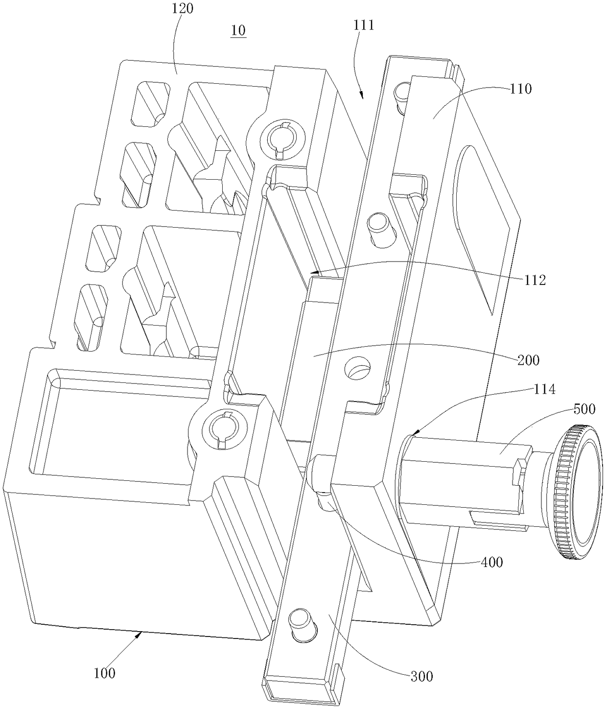
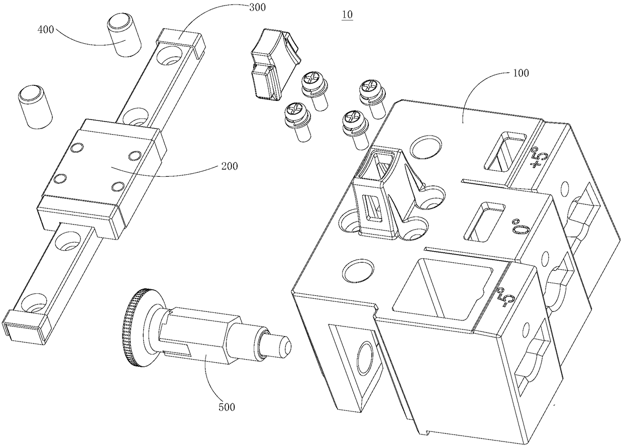
The invention relates to a sliding block angle lock and a display screen. The sliding angle lock comprises a sliding block, a support block, a guide rail, a positioning pin and an inserting pin. The sliding block comprises a mounting portion and a locking portion connected with the mounting portion. Multiple locking faces are arranged on the locking portion. An included angle is formed between every two adjacent locking faces. A locking hole is formed in each locking face. A sliding groove is formed in the mounting portion. A mounting groove communicating with the sliding groove is formed in the mounting portion. A mounting hole communicating with the sliding groove is formed in the mounting portion. The support block is contained in the mounting groove. The guide rail is slidably arranged in the sliding groove. The guide rail is slidably connected with the support block. A limiting hole is formed in the guide rail. The positioning pin penetrates the limiting hole. The inserting pin penetrates the mounting hole. According to the sliding block angle lock, the jacking and locking operations are performed by flexibly selecting different locking faces and jacking faces, the splicing requirements of multiple inclination angles can be met, and the universality is high.

Description

technical field [0001] The invention relates to the technical field of display screen installation, in particular to a slider angle lock and a display screen. Background technique [0002] At present, the application requirements of LED display screens are becoming more and more extensive. Among them, there are more and more demands for special-shaped splicing screens, and the requirements are becoming more and more stringent. In many venues and performance occasions, it is necessary to splice screens with curvature. The screen body is formed by a plurality of screen body units, which requires a certain angle between two adjacent screen body units. [0003] In the prior art, there are the following problems in the arc splicing of the LED display screen: the side edge of the main cabinet of the LED display is processed with an inclined splicing surface. When the two main cabinets are spliced, the two main cabinets will An included angle is formed to achieve the effect of rad...

Claims


Application Information

Patent Timeline
Patent Type & Authority Patents(China)
IPC IPC(8): F16B5/10G09F9/33
CPCF16B5/0092G09F9/33
Inventor 颜小平李大政
Owner SHENZHEN EASTAR ELECTRONICS
Learn More