
A Calculation Method of Feature Points of Curved Reinforcement Cage

A calculation method and steel cage technology, applied in design optimization/simulation, geometric CAD, CAD numerical modeling, etc., can solve the problem that it is difficult to determine the relative position of the binding operation platform and the steel cage in advance, it is difficult to connect the steel cage, and it is difficult to connect each section. segment positioning and other issues, to achieve the effect of fast point placement on site, avoiding low efficiency, and good splicing

Inactive Publication Date: 2020-10-16
CCCC FOURTH HARBOR ENG CO LTD +3
View PDF2 Cites 0 Cited by
  • Summary
  • Abstract
  • Description
  • Claims
  • Application Information

AI Technical Summary

Problems solved by technology

[0004] When binding on each binding platform, it is necessary to place points on the characteristic points of the reinforcement cage through measuring instruments. The position of each segment is different, so it is difficult to locate each segment on each binding platform, which makes it difficult for the steel cage after binding to be well connected with the previous segment quickly. Therefore, how to determine the position of the reinforcement cage on each binding platform The characteristic points during the upper binding become the key to realize the butt joint of each segment of the reinforcement cage in the curved section. The characteristic points of the reinforcement cage refer to the positioning points used to determine the binding position of the reinforcement cage, and the characteristic points are the points on the reinforcement cage , through the feature points and the design shape of the reinforcement cage, the binding position and binding shape of the reinforcement cage can be determined
[0005] At the same time, when binding the reinforcement cage on each binding platform, it is necessary to ensure the relative position between the binding operation platform and the reinforcement cage, so as to facilitate the construction work of the binding operators, and the position of each segment forming the curved section of the immersed tube is different, resulting in It is difficult to determine the relative position of the lashing operation platform and the reinforcement cage in advance, and the lashing operation can only be adjusted after the reinforcement cage is pushed into place to make it fit the reinforcement cage, which will greatly reduce the construction efficiency and prolong the construction period

Method used


Image

  • A Calculation Method of Feature Points of Curved Reinforcement Cage
  • A Calculation Method of Feature Points of Curved Reinforcement Cage
  • A Calculation Method of Feature Points of Curved Reinforcement Cage

Examples


Embodiment 1

[0064] This embodiment is applied to the occasion of determining the characteristic points of the steel cage in the curved section.

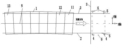
[0065] Such as image 3 with Figure 4 As shown, the calculation method of the characteristic points of the steel cage in the curve segment includes the following steps:

[0066] a, establish a coordinate system, set up the planar Cartesian coordinate system of the immersed tube reinforcement cage binding platform 6 and the jacking system in the drawing software, and the jacking system in the present embodiment is the jacking girder 3;

[0067] b, arrange reference control points, set a plurality of reference control points 4 on the site binding platform, and mark a plurality of reference control points 4 on the binding platform 6, so that the position coordinates of the reference control points 4 are fixed;

[0068] c. Arrange the push track control point 5, arrange the push track control point 5 on the site binding platform 6, and arrange th...

Embodiment 2

[0084] This embodiment illustrates the process of using the method in Embodiment 1 to determine the feature points of the curved segment reinforcement cage wall segment.

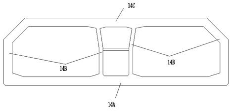
[0085] Such as Image 6 , Figure 7 , Figure 8 with Figure 9 As shown, when the wall section 14B of the curved section immersed pipe 1 is bound, the process of determining the feature points specifically includes the following steps:

[0086] Step 1.1, drawing, draw the wall section binding platform 6, the wall back frame 7 and the pushing girder 3 for pushing the reinforcement cage in the coordinate system, the coordinate system adopts the coordinates established in step a in embodiment 1 system, the wall back frame 7 is an operating platform for binding the steel cage of the wall section, and the position of the pushing girder 3 is the position before pushing;

[0087] Step 1.2, on-site jacking, jacking the floor reinforcement cage to the pre-marked jacking stop mark line, and measuring the jacking l...

Embodiment 3

[0098] This embodiment illustrates the calculation process for determining the characteristic points of the roof section of the immersed tube in the curved section and the position of the chamfering template of the roof section.

[0099] Adopt the calculation method identical with embodiment 1 or embodiment 2 to determine the feature point of the roof section, and complete on-the-spot setting point according to this feature point, carry out binding, specifically comprise the following steps:

[0100] Step 2.1, drawing, draw the roof section binding platform, the roof binding support frame and the pushing girder for pushing the steel cage in the coordinate system, which is the coordinate system established in step a in embodiment 1, the roof The position of the push girder is the position before the push;

[0101] Step 2.2, on-site jacking, push the wall reinforcement cage to the pre-marked jacking stop mark line, and measure the jacking length of the jacking girder;

[0102] ...


PUM


Abstract

The invention relates to the technical field of immersed tube tunnels, in particular to a calculation method of curved section reinforcement cage feature points. The method comprises the following steps that 1, a binding platform and a rectangular coordinate system are built in cartographic software; 2, a plurality of reference control points and pushing track control points are arranged on the site binding platform, and a pushing track is distributed through the track control points in the pushing direction; 4, a curved section immersed tube, a pushing track and the control points and the reference control points of a pushing track are drawn; 5, section pushing is simulated, the section is moved to the pushing track control points, and coordinates of feature points of a section are measured; 6, according to the coordinates of feature points obtained in the fifth step, site point release is conducted. According to the calculation method, the problem of difficult splicing of adjacent sections caused by single adoption of site point measurement and release can be solved, the binding position of each section can be precisely and quickly determined, the speed and precision of site measurement are improved, it is guaranteed that each section is in butt joint with the previous stage after blinding is completed, and the butt joint precision is within the controllable range.

Description

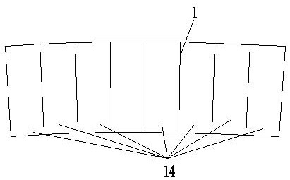
technical field [0001] The invention relates to the technical field of immersed tube tunnels, in particular to a calculation method for characteristic points of a steel cage in a curved section. Background technique [0002] When building a cross-sea bridge with immersed tube sections, the transition section from the immersed tube section to the bridge section is a curved section, and the curved section includes multi-section curved section immersed tubes. It is prefabricated in the prefabrication factory, and then consigned to the site by barge for installation. [0003] Each section of immersed tube is spliced ​​by multiple segments. During the manufacturing process of immersed tube, a single segment is manufactured one by one, and then multiple segments are spliced ​​end to end to form a complete immersed tube. Such as figure 1 As shown, the single segment 14 constituting the curved segment immersed tube 1 is linear, the overall shape of the segment 14 is a trapezoidal ...

Claims


Application Information

Patent Timeline
Patent Type & Authority Patents(China)
IPC IPC(8): G06F30/20G06F30/13G06F111/10
Inventor 邹正周陈伟彬黄文慧董政陈聪朱成
Owner CCCC FOURTH HARBOR ENG CO LTD
Learn More