Novel differential

A differential, a new type of technology, applied in the direction of differential transmission, belt/chain/gear, mechanical equipment, etc., can solve the problems of complex structure and high cost of differential

Pending Publication Date: 2017-12-08
孙超
View PDF0 Cites 1 Cited by
  • Summary
  • Abstract
  • Description
  • Claims
  • Application Information

AI Technical Summary

Problems solved by technology

Therefore, the existing differential

Method used


Image

  • Novel differential
  • Novel differential
  • Novel differential

Examples


Example Embodiment

[0018] Example 1:

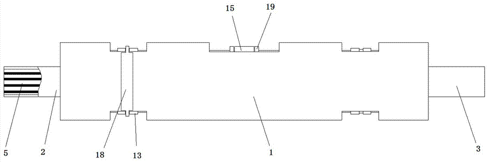
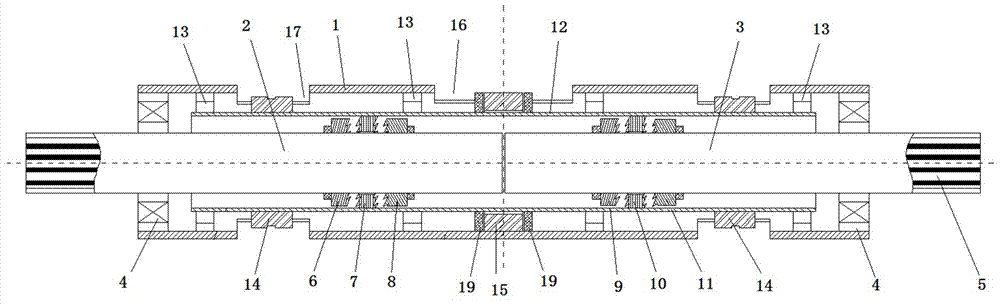
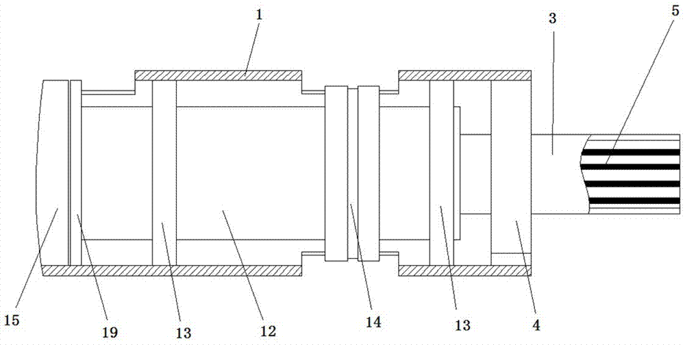
[0019] like figure 1 , figure 2 , image 3 and Figure 4 As shown in the figure, a new type of differential includes a casing 1, a lubricating oil is arranged in the casing, a left output half shaft 2 and a right output half shaft 3 are arranged in the casing 1, and the left output half shaft 2 and the right output half shaft are arranged in the casing 1. The shaft 3 is erected inside the casing 1 through the bearing 4, the left output half shaft 2 and the right output half shaft 3 are coaxial, and there is no contact between them, and the left output half shaft 2 and the right output half shaft 3 protrude to the casing 1. The outer shaft is arranged in the axial direction as a middle and empty inner spline slot 5, and the inner spline slot 5 is used for transmission between the axle shaft of the automobile.

[0020] A first left half shaft gear 6, a first transmission gear 7, and a second left half shaft gear 8 are sleeved on the outer circular surfac...

Example Embodiment

[0027] Example 2:

[0028] Under the condition that other structures in the device are the same, the first left side gear and the second left side gear are both ratchet mechanisms, the rotation directions of the two ratchet mechanisms are opposite, and the first transmission gear is located in the first Between the left side gear and the second left side gear, the left and right sides of the first transmission gear are respectively set as hollow sleeves, the inner circular surface of the sleeve is provided with teeth, and the teeth on the left and right sides of the first transmission gear can be respectively Meshes with the teeth in the ratchet mechanism. The shape and specification of the first right side gear and the first left side gear are exactly the same, the shape and specification of the second right side gear and the second left side gear are exactly the same, and the second transmission gear is located on the first right side. Between the gear and the second right ...


PUM


Abstract

The invention belongs to the field of auto parts, and in particular relates to a new type of differential gear, which includes a casing, a left output half shaft and a right output half shaft are arranged in the casing, and the outer circle of the left output half shaft is sequentially fitted with The first left side shaft gear, the first transmission gear, the second left side shaft gear, the first left side shaft gear and the second left side shaft gear are fixed on the outer circular surface of the left output shaft shaft, the first left side shaft gear The rotation direction of the teeth on the second left side shaft gear is opposite to that on the left and right sides of the first transmission gear. There are teeth meshing with the first left side shaft gear and the second left side shaft gear respectively; the structure on the right output side shaft The structure is the same as that on the left output half-shaft, the outside of the left and right output half-shafts is wrapped with a drive sleeve, and the drive sleeve can slide along the axis of the left output half-shaft; the inner wall of the drive sleeve is respectively connected to the first The transmission gear and the second transmission gear are connected; the outer wall of the transmission sleeve is provided with a shift fork ring and a driven ring gear, and the device has a simple structure and low cost.

Description

technical field [0001] The invention belongs to the field of auto parts, in particular to a novel differential gear. Background technique [0002] The car differential is the main part of the drive car. Its function is to transmit power to the two half shafts, while allowing the two half shafts to rotate at different speeds, so that the wheels on both sides can run at unequal distances in the form of pure rolling as much as possible, reducing the friction between the tires and the ground. The power of the car engine is transmitted through the clutch, transmission, transmission shaft, and finally to the drive axle and then distributed to the left and right axle drive wheels. On this power transmission path, the drive axle is the last assembly, and its main components are the reducer and The differential is used for deceleration, distance increase and differential function. The differential is generally composed of planetary gears, planetary carrier (differential housing), s...

Claims


Application Information

Patent Timeline
IPC IPC(8): F16H48/12F16H48/24F16H48/32F16H48/34
CPCF16H48/12F16H48/24F16H48/32F16H48/34F16H2048/202
Inventor 孙超
Owner 孙超
Why Eureka
Try Eureka