[0021] In order to make the technical means, creative features, objectives and effects of the present invention easy to understand, the present invention will be further explained below in conjunction with specific embodiments.
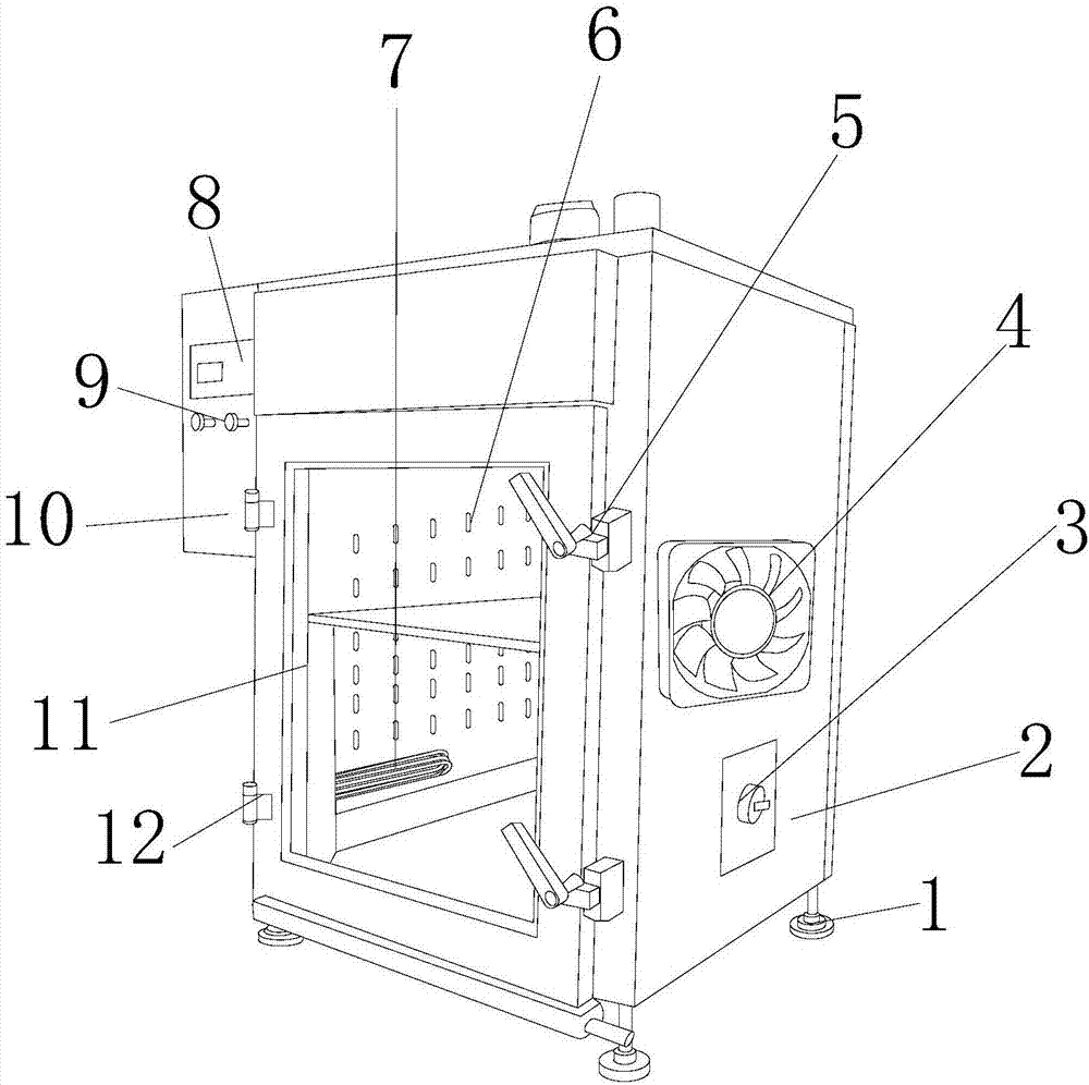
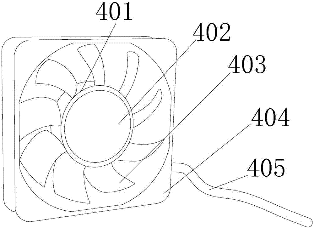
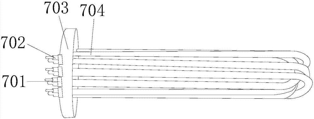
[0022] See figure 1 , figure 2 versus image 3 , The present invention provides a technical solution for smoked food equipment: its structure includes a foot 1, a box body 2, a smoking box 3, a cooling fan 4, a lock 5, a smoking hole 6, an electric heating tube 7, and a display screen. 8. Operation button 9, electric control box 10, box inner wall 11, rotary buckle 12, the bottom feet 1 are provided with four and are respectively installed at the bottom of the box body 2, and the right side of the box body 2 is provided with a smoke generator Box 3, the smoking box 3 and the box body 2 adopt a clearance fit, and the front face of the box body 2 is provided with a lock 5;
[0023] The lock catch 5 and the box body 2 adopt a clearance fit, and the box body 2 is provided with a box inner wall 11 inside, and the box inner wall 11 and the box body 2 are an integrated structure, and the box inner wall 11 is fixed There is a smoking hole 6, an electric heating tube 7 is installed at the bottom of the smoking hole 6, a rotating buckle 12 is provided on the left front face of the box body 2, and the rotating buckle 12 and the box body 2 adopt a gap In cooperation, an electric control box 10 is installed on the left side of the box body 2, the electric control box 10 is fixedly provided with a display screen 8, and the bottom of the display screen 8 is provided with an operating button 9, the operating button 9 is electrically connected to the display screen 8;
[0024] The cooling fan 4 is fixed on the right side of the box body 2, and the cooling fan 4 is electrically connected to the operation button 9. The cooling fan 4 is composed of a rotating shaft 401, an axial fan 402, a fan blade 403, and an outer casing. 404, electrical wiring 405, the axial fan 402 is arranged inside the rotating shaft 401, the rotating shaft 401 and the axial fan 402 adopt clearance fit, the outer surface of the rotating shaft 401 is provided with fan blades 403, The fan blade 403 and the rotating shaft 401 are an integrated structure. The outer side of the fan blade 403 is fixed to the outer casing 404. The bottom right side of the outer casing 404 is provided with an electric connection 405, and the electric connection 405 It is electrically connected to the axial flow fan 402. The axial flow fan 402 is electrically connected to the operation button 9 through the electrical connection 405. The electric heating tube 7 is composed of a conductive block 701, an electric pole 702, a connecting plate 703, and a heating tube 704. The conductive block 701 is arranged at the bottom of the power connection post 702, the power connection post 702 and the conductive block 701 are an integrated structure, and the bottom of the conductive block 701 is fixedly provided with a connection pad 703, and the connection A heating tube 704 is installed at the bottom of the tray 703, the operation button 9 is electrically connected to the electric heating tube 7, and the fan blade 403 is curved.
[0025] The axial flow fan 402 described in this patent has a very wide range of uses, that is, the airflow in the same direction as the axis of the blade, such as an electric fan, an air conditioner external fan is an axial flow fan.
[0026] During use, the user mixes the smoking material and sugar in an appropriate ratio and then adds the smoking box 3, then operates the button to set the appropriate smoking time and smoking temperature, and heats the smoking material through the electric heating tube 7 Perform incomplete combustion, and then emit smoke from the smoke hole 6. For example, a smoker in Jiacun has low smoking effect and low heat dissipation performance of the cabinet, which causes the heat dissipation to fail to keep up with the heat and the cabinet stays in a hot state for a long time , Affect the service life of the device, then you can use the present invention to have a radiating fan composed of a rotating shaft, an axial fan 4, a fan blade, an outer casing, and electrical wiring, which can speed up the heat dissipation of the box and keep the heat dissipation parallel to the heat generation , Increase the service life of the device, and improve the working efficiency of the device to a certain extent.
[0027] The foot 1, the box body 2, the smoking box 3, the cooling fan 4, the lock catch 5, the smoking hole 6, the electric heating tube 7, the display screen 8, the operation button 9, the electric control box 10, the inner wall of the box 11, The rotating buckle 12, the rotating shaft 401, the axial fan 402, the fan blade 403, the outer casing 404, the electrical wiring 405, the conductive block 701, the connection post 702, the connection plate 703, and the heating tube 704 are all common standard parts or in the field The structure and principle of the components known by the technicians are all known to the technicians through technical manuals or through conventional experimental methods. The problem solved by the present invention is low in smoking effect and low heat dissipation performance of the cabinet, resulting in poor heat dissipation. The upper heating keeps the box in a hot state for a long time and affects the service life of the device. Through the combination of the above-mentioned components, the present invention is provided with a radiating fan consisting of a rotating shaft, an axial fan 4, a fan blade, an outer casing, and electrical wiring. Speed up the heat dissipation of the box, keep the heat dissipation parallel to the heat, increase the service life of the device, and improve the working efficiency of the device to a certain extent, as follows:
[0028] The cooling fan 4 is fixed on the right side of the box body 2, and the cooling fan 4 is electrically connected to the operation button 9. The cooling fan 4 is composed of a rotating shaft 401, an axial fan 402, a fan blade 403, and an outer casing. 404, electrical wiring 405, the axial fan 402 is arranged inside the rotating shaft 401, the rotating shaft 401 and the axial fan 402 adopt clearance fit, the outer surface of the rotating shaft 401 is provided with fan blades 403, The fan blade 403 and the rotating shaft 401 are an integrated structure, and the outer side of the fan blade 403 is fixed to the outer casing 404, and the bottom of the right side of the outer casing 404 is provided with an electric connection 405, the electric connection 405 It is electrically connected to the axial flow fan 402, and the axial flow fan 402 is electrically connected to the operation button 9 through the electrical connection 405.
[0029] The above shows and describes the basic principles and main features of the present invention and the advantages of the present invention. For those skilled in the art, it is obvious that the present invention is not limited to the details of the above exemplary embodiments, and does not deviate from the spirit or basics of the present invention. In the case of features, the present invention can be implemented in other specific forms. Therefore, from any point of view, the embodiments should be regarded as exemplary and non-limiting. The scope of the present invention is defined by the appended claims rather than the foregoing description, and therefore it is intended to fall within the claims. All changes within the meaning and scope of equivalent elements of are included in the present invention. Any reference signs in the claims should not be regarded as limiting the claims involved.
[0030] In addition, it should be understood that although this specification is described in accordance with the embodiments, not every embodiment only includes an independent technical solution. This narration in the specification is only for clarity, and those skilled in the art should consider the specification as a whole The technical solutions in the embodiments can also be appropriately combined to form other implementations that can be understood by those skilled in the art.