Vehicle omni-bearing auxiliary parking device
A kind of auxiliary parking, all-round technology, applied in the direction of vehicle cleaning equipment, etc., can solve the problems of car scraping and waste, and achieve the effect of saving space, simple operation and high cost performance.
- Summary
- Abstract
- Description
- Claims
- Application Information
AI Technical Summary
Problems solved by technology
Method used
Image
Examples
Embodiment 1
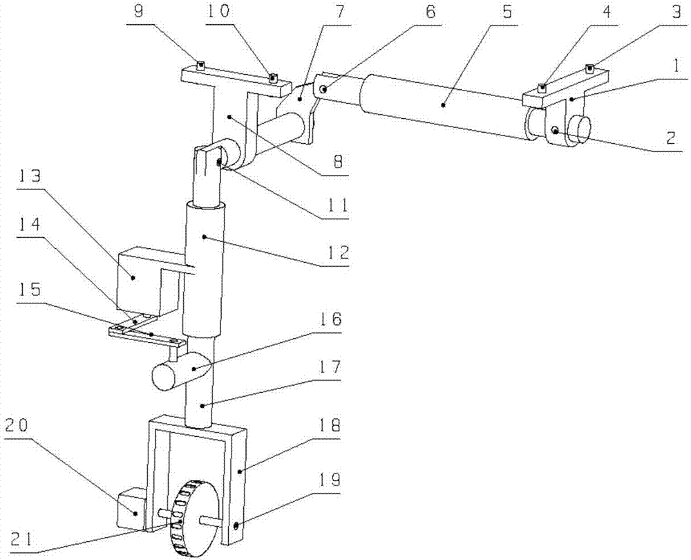
[0014] As shown in Figure 1, an all-round auxiliary parking device for automobiles in the present invention includes a fixed support 1 fixed to the chassis of the vehicle through fixed bolts I3 and fixed bolts II4, and the lower end of the fixed support 1 is connected to the horizontal electric pusher through the connecting shaft pin I2. One end of the rod 5 is connected, and the other end of the horizontal electric push rod 5 is connected with the upper right of the rocker part of the movable rocker arm I7 through the connecting pivot pin II6. One end of the rocker of the movable rocker arm 7 close to the vertical electric push rod 12 is nested in the fixed bearing support 8, and the end of the movable rocker arm 7 is connected to the vertical electric push rod 12 through the pivot pin III11. connected, the vertical electric push rod 12 is equipped with a steering gear 13, and the steering gear 13 is fixedly connected with the bracket rotating shaft 17 through the first connec...
Embodiment 2
[0017] Based on Embodiment 1, the horizontal electric push rod 5 is controlled to shrink to the end, and the movable rocker lever 7 drives the vertical electric push rod 12 to rotate downward under the action of the horizontal electric push rod 5, and then the vertical electric push rod 12 stretches out until it is vertical The electric push rod 12 and the supporting wheel 21 support the overall body of the automobile, so that the automobile wheels leave the ground at a certain distance and stop automatically.
Embodiment 3
[0019] Based on the first embodiment above, the steering gear 13 can be controlled to make the support wheel 21 turn rightward or leftward, so that the car moves rightward or leftward.
[0020] Control the vertical electric push rod 12 to shrink upwards to the end, and now the left end of the control horizontal electric push rod 5 stretches out a certain distance to the left, and the movable rocker arm 7 rotates downward under the action of the horizontal electric push rod 5, and simultaneously because A fixed bearing support is installed on the movable rocker arm 7, so it is easier to rotate the movable rocker arm 7; at the same time, the movable rocker arm 7 will drive the vertical electric push rod 12 and the supporting wheel 21 to be transferred upward to the bottom of the vehicle Parallel with the chassis, now the horizontal electric push rod 5 stops working and records the distance that the left end of the horizontal electric push rod 5 stretches out to the left.
PUM
 Abstract
Description
Claims
Application Information
 - R&D
- Intellectual Property
- Life Sciences
- Materials
- Tech Scout
- Unparalleled Data Quality
- Higher Quality Content
- 60% Fewer Hallucinations
Browse by: Latest US Patents, China's latest patents, Technical Efficacy Thesaurus, Application Domain, Technology Topic, Popular Technical Reports.
© 2025 PatSnap. All rights reserved.Legal|Privacy policy|Modern Slavery Act Transparency Statement|Sitemap|About US| Contact US: help@patsnap.com

