Ultrasonic flaw detection device for steel rail base metal rail flange

A flaw detection device and ultrasonic technology, which are applied in measurement devices, material analysis using sonic/ultrasonic/infrasonic waves, and material analysis, etc., can solve the problems of not ensuring flaw detection quality, affecting rail flaw detection, affecting rail transportation safety, etc., and achieving flaw detection process. Smooth and reliable, convenient and quick to adjust, easy to install and operate

Pending Publication Date: 2017-12-12
四川曜诚无损检测技术有限公司 +1
View PDF0 Cites 16 Cited by
  • Summary
  • Abstract
  • Description
  • Claims
  • Application Information

AI Technical Summary

Problems solved by technology

[0002] Rail bottom flaw detection is of great significance to the safety of rail transportation. Before the formal flaw detection operation on the rail bottom, it is necessary to adjust the flaw detection structure horizontally and vertically to ensure that the flaw detection structure is in a proper position relative to the rail. The existing flaw detection device adjustment It is cumbersome, low in efficiency, and the effect is not good; secondly, in the process of flaw d

Method used


Image

  • Ultrasonic flaw detection device for steel rail base metal rail flange
  • Ultrasonic flaw detection device for steel rail base metal rail flange
  • Ultrasonic flaw detection device for steel rail base metal rail flange

Examples


Embodiment 1

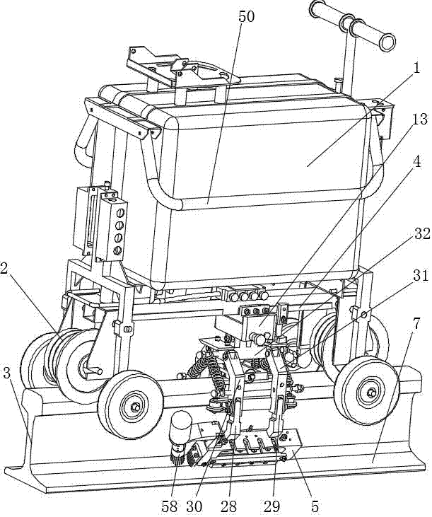
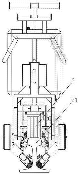
[0033] Such as Figures 1 to 5As shown in . and 9, an ultrasonic flaw detection device for rail bottom of a rail parent material, including a trolley 1 and a flaw detection structure, the front and rear ends of the bottom of the trolley 1 are provided with track wheels 2, and the track wheels 2 are supporting rolling wheels for the trolley 1 on the tread surface of the rail 3 , to support and guide the trolley 1 moving forward on the rail 3. The flaw detection device also includes a clamping mechanism. The clamping mechanism is arranged on the crossbeam 4 at the bottom of the trolley 1 and can be slid and adjusted longitudinally relative to the crossbeam 4. The flaw detection structure is connected to the clamping mechanism. the lower part of the institution;

[0034] The flaw detection structure includes two sets of probe racks 5 arranged on both sides of the rail 3 and probes 6 installed in the probe racks 5. When the flaw detection device is installed on the rail 3, the cor...

Embodiment 2

[0043] Such as Figures 1 to 9 As shown, on the basis of Embodiment 1, the flaw detection device also includes a landing mechanism. The landing mechanism includes a landing gear mounting seat 32, a front landing gear 30, and a rear landing gear 31. The landing gear mounting seat 32 is fixedly connected to the compensation rod 20. 1. One end of the rear landing gear 30,31 is rotatably connected to the front and rear ends of the landing gear mount 32 respectively. Symmetry, the other end of the front landing gear 30 is connected with the front connecting rod 28, the other end of the rear landing gear 31 is connected with the rear connecting rod 29, and the front and rear connecting rods 28, 29 are respectively on the front and rear landing gears 30, 31. The installation height is adjustable, and the flaw detection structure is fixedly connected with the front and rear connecting rods 28, 29, that is, the two sets of probe racks 5 are fixedly connected with the corresponding fron...

Embodiment 3

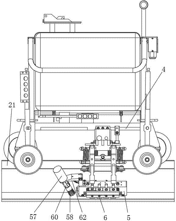
[0050] Such as Figures 1 to 3 , 9, in order to make the flaw detection effect better, on the basis of Embodiment 2, the front end of the probe frame 5 is provided with a rail 3 cleaning structure, and the rail 3 cleaning structure includes a motor 57, a steel brush head 58 and a motor fixing seat 59, and the motor 57 is set on the front end of the probe frame 5 through the motor fixing seat 59, and the steel brush head 58 is connected to the end of the motor 57 through the coupling 60. Downward automatic compensation adjustment; it also includes a brush 63 arranged on the front end of the probe frame 5, the brush 63 is located behind the steel brush head 58, and the brush 63 is closely attached to the area to be tested; specifically, the motor 57 passes through the motor mounting plate 64 is connected with motor mount 59, and motor 57 is fixedly mounted on the front end of motor mounting plate 64, and the rear end of motor mounting plate 64 is connected with motor mount 59 in...


PUM


Abstract

The invention relates to the technical field of in-service rail flaw detection, and discloses an ultrasonic flaw detection device for the rail bottom of the rail parent material, which includes a trolley and a flaw detection structure. Rail wheels are arranged at the front and rear ends of the bottom of the trolley, and the rail wheels are supported and rolled by the trolley on the rail tread. The wheel also includes a clamping mechanism. The clamping mechanism is arranged on the beam at the bottom of the trolley and can be slid and adjusted longitudinally relative to the beam. The clamping mechanism includes a horizontal adjustment bolt, and the flaw detection structure is connected to the clamping In the lower part of the mechanism, the lateral adjustment bolt can adjust the lateral movement of the flaw detection structure. The invention has the advantages of convenient installation and operation, convenient adjustment, high efficiency, good effect, stable and reliable operation, and little external interference.

Description

technical field [0001] The invention relates to the technical field of flaw detection of in-service rails, in particular to an ultrasonic flaw detection device for the base material of the rail. Background technique [0002] Rail bottom flaw detection is of great significance to the safety of rail transportation. Before the formal flaw detection operation on the rail bottom, it is necessary to adjust the flaw detection structure horizontally and vertically to ensure that the flaw detection structure is in a proper position relative to the rail. The existing flaw detection device adjustment It is cumbersome, low in efficiency, and the effect is not good; secondly, in the process of flaw detection operation, the lateral shaking of the flaw detection trolley will also affect the smooth flaw detection of the flaw detection structure on the rail; The wear condition of the trolley is also different, so there will be some ups and downs when the trolley is moving forward, which seri...

Claims


Application Information

Patent Timeline
IPC IPC(8): B61K9/10B61D15/08G01N29/22
CPCG01N29/225B61D15/08B61K9/10G01N2291/0234
Inventor 袁刚强李浩王科刘亚仑赵世伟曾路程黄学龙周双段宇李想胡传武王泽斌刘长青曾富周雪清
Owner 四川曜诚无损检测技术有限公司
Why Eureka
Try Eureka