Adjustment method and device of head-mounted display device, and head-mounted display device
A technology for display equipment and adjustment methods, applied in optical components, optics, instruments, etc., can solve problems such as insufficient manual adjustment accuracy, affecting user viewing effect, and misalignment of screen center points, achieving a good user experience effect and improving equipment. Adjustment method, the effect of optimizing the display effect
- Summary
- Abstract
- Description
- Claims
- Application Information
AI Technical Summary
Problems solved by technology
Method used
Image
Examples
Embodiment 1
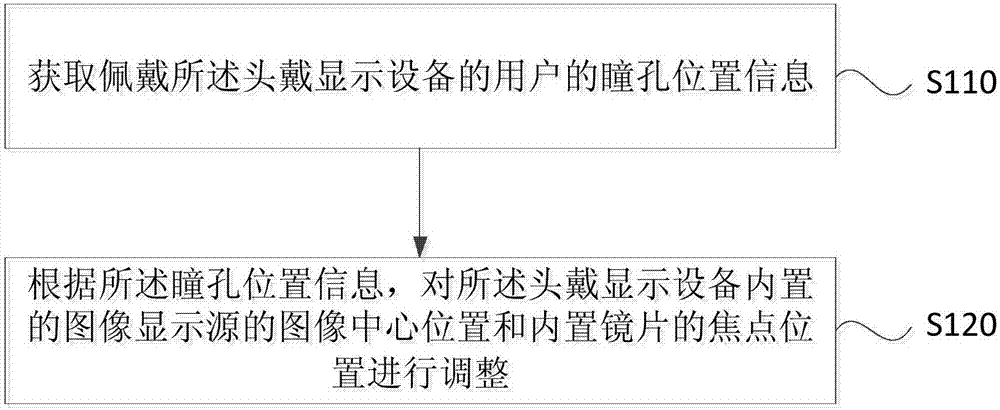
[0025] figure 1 The flow chart of the adjustment method of the head-mounted display device provided by Embodiment 1 of the present invention, this embodiment is applicable to the adjustment of the head-mounted display device, the method can be executed by the adjustment device of the head-mounted display device, and the device can adopt implemented in software and / or hardware. like figure 1 As shown, the method specifically includes the following steps:
[0026] S110. Acquire pupil position information of a user wearing the head-mounted display device.
[0027] Wherein, the pupil position information is the distance between the pupils of the two eyes of the user wearing the head-mounted display device. Generally speaking, different users will have different visual effects when wearing a head-mounted display device, and the head-mounted display device should be adaptively adjusted according to the pupillary distance of each user to achieve the best visual effect. There are ...
Embodiment 2
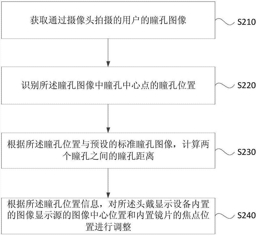
[0033] figure 2 It is a flow chart of the adjustment method of the head-mounted display device provided by Embodiment 2 of the present invention. This embodiment is optimized on the basis of the above-mentioned embodiments. Specifically, the pupil position information of the user wearing the head-mounted display device will be obtained. , specifically optimized as follows: acquiring a pupil image of the user captured by a camera; and identifying the pupil image to acquire the pupil position information. The pupil image will be identified to obtain the pupil position information, which is further optimized to: identify the pupil position of the pupil center point in the pupil image; calculate two Pupil distance between pupils. see figure 2 , the method specifically includes:
[0034] S210. Acquire a pupil image of the user captured by a camera.
[0035] A camera is arranged on the head-mounted display device, and a small infrared diode is embedded beside or inside the len...
Embodiment 3
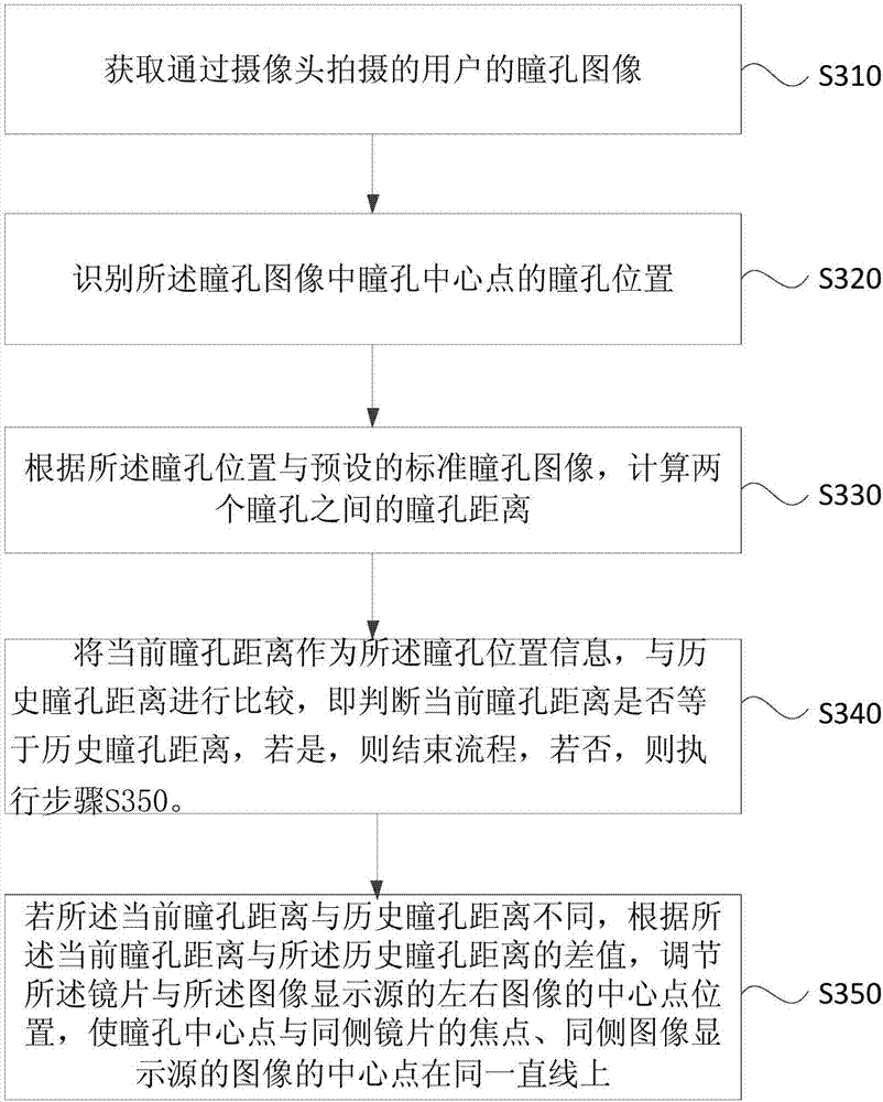
[0045] image 3 The flow chart of the adjustment method of the head-mounted display device provided by Embodiment 3 of the present invention. This embodiment is optimized on the basis of the above-mentioned embodiments. Specifically, the head-mounted display The image center position of the built-in image display source of the device and the focus position of the built-in lens are adjusted, and the specific optimization is as follows: the current pupillary distance is used as the pupil position information, and compared with the historical pupillary distance; if the current pupillary distance and the historical pupillary distance If the distance is different, according to the difference between the current pupillary distance and the historical pupillary distance, adjust the position of the center point of the lens and the left and right images of the image display source, so that the center point of the pupil is the focus of the lens on the same side, the same side The image s...
PUM
 Abstract
Description
Claims
Application Information
 - R&D
- Intellectual Property
- Life Sciences
- Materials
- Tech Scout
- Unparalleled Data Quality
- Higher Quality Content
- 60% Fewer Hallucinations
Browse by: Latest US Patents, China's latest patents, Technical Efficacy Thesaurus, Application Domain, Technology Topic, Popular Technical Reports.
© 2025 PatSnap. All rights reserved.Legal|Privacy policy|Modern Slavery Act Transparency Statement|Sitemap|About US| Contact US: help@patsnap.com


