Charging control method, charger, terminal and computer readable storage medium

A charging control method and charging control technology, which are applied in the communication field and can solve the problems that terminals cannot realize intelligent control, etc.

Active Publication Date: 2017-12-12
NUBIA TECHNOLOGY CO LTD
View PDF7 Cites 6 Cited by
  • Summary
  • Abstract
  • Description
  • Claims
  • Application Information

AI Technical Summary

Problems solved by technology

[0003] The main purpose of the present invention is to propose a charging control method, a charger, a terminal, and a computer-readable storage medium, aiming to solve the problem that intelligent control cannot be realized in the terminal charging process in the prior art

Method used


Image

  • Charging control method, charger, terminal and computer readable storage medium
  • Charging control method, charger, terminal and computer readable storage medium
  • Charging control method, charger, terminal and computer readable storage medium

Examples


Embodiment 1

[0071] The invention provides a charging control method on the charger side.

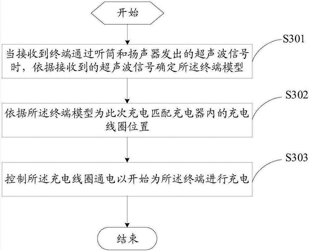
[0072] Please refer to image 3 , which is a schematic flow chart of the charging control method on the charger side provided by the first embodiment of the present invention, which is mainly used in the charger, and the method includes steps:

[0073] Step S301, when receiving the ultrasonic signal sent by the terminal through the handset and the speaker, determine the terminal model according to the received ultrasonic signal;

[0074] Specifically, in the present invention, the communication between the terminal and the charger can be realized through ultrasonic waves. When the charger receives the ultrasonic signal sent by the terminal, it can determine the model of the terminal according to the received ultrasonic signal. Here, the model of the terminal mainly refers to the actual position of the coil of the terminal when different types of terminals are in different charging positions. The ...

Embodiment 2

[0098] In addition, the present invention provides a charger. See Figure 10 , the charger 300 includes a processor 301 , a memory 302 and a communication bus 303 . Wherein the communication bus 83 is used to realize the connection and communication between the processor 301 and the memory 302, the memory 301 is a computer-readable storage medium in which a charging control program is stored, and the processor 301 can implement the following steps 1 by executing the computer program -3:

[0099] Step 1, when receiving the ultrasonic signal sent by the terminal through the handset and the speaker, determine the terminal model according to the received ultrasonic signal;

[0100] Specifically, in the present invention, the communication between the terminal and the charger can be realized through ultrasonic waves. When the charger receives the ultrasonic signal sent by the terminal, it can determine the model of the terminal according to the received ultrasonic signal. Here,...

Embodiment 3

[0126] The present invention further provides a computer-readable storage medium, where a charging control program is stored on the computer-readable storage medium, and when the charging control program is executed by a processor, the charging control method introduced in the first embodiment above is implemented.


PUM


Abstract

The invention discloses a charging control method, a charger, a terminal and a computer readable storage medium, belonging to the technical field of communication. The method comprises the following steps: determining the terminal model according to a received ultrasonic signal when the ultrasonic signal which is transmitted by the terminal through a receiver and a speaker is received; and matching the position of a charging coil in the charger for the charging according to the terminal model; and controlling the charging coil to be electrified to charge the terminal. Therefore, the charger and the terminal are in communication through ultrasonic signals, the terminal module is determined, and the position of the charging coil is matched for the terminal to realize smart charging. The terminal can be started to charge in a wireless manner on an arbitrary position through ultrasonic, a user does not need manually adjust the terminal placement position or manually plug a charging wire.

Description

technical field [0001] The present invention relates to the technical field of communication, and in particular to a charging control method, a charger, a terminal and a computer-readable storage medium. Background technique [0002] At present, terminals such as mobile phones have become a must-have for everyone. Due to the increase in frequency and time of use, the power requirements for terminals are also getting higher and higher. In addition to fast charging, convenience and intelligent charging are also required. . In the prior art, when the terminal is charging, it is basically connected with the charger by a data line. Except for charging, there is basically no communication function during charging, and it is impossible to automatically control the charging process through the communication between the terminal and the charger, and there is no intelligent charging protection. , and the current charging of the terminal basically relies on manual plugging. When charg...

Claims


Application Information

Patent Timeline
Patent Type & Authority Applications(China)
IPC IPC(8): H02J7/00H02J50/90
CPCH02J7/0088H02J7/025H02J50/90H02J7/00034H02J7/00036
Inventor 丁火根
Owner NUBIA TECHNOLOGY CO LTD
Why Eureka
Try Eureka