
Positioning of an examination object for an imaging method

An imaging method and object technology, applied in patient positioning for diagnosis, instruments and applications for radiological diagnosis, etc., can solve problems such as poor organizational cognitive prerequisites, insufficient operator training, and damage to the quality of patient examinations. The effect of short scan duration, extensive use, and positioning optimization

Inactive Publication Date: 2017-12-15
SIEMENS HEALTHCARE GMBH
View PDF8 Cites 7 Cited by
  • Summary
  • Abstract
  • Description
  • Claims
  • Application Information

AI Technical Summary

Problems solved by technology

However, even with this assist function, the user must be familiar with the proper positioning of the patient
In many underdeveloped regions of the world, although medical imaging facilities (such as, for example, CT systems) are now available, operators are often undertrained due to poor organization and lack of cognitive prerequisites, and this can compromise the quality of patient examinations

Method used


Image

  • Positioning of an examination object for an imaging method
  • Positioning of an examination object for an imaging method
  • Positioning of an examination object for an imaging method

Examples


Embodiment Construction

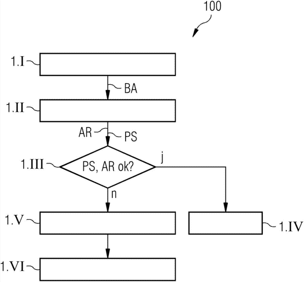
[0070] figure 1 A flowchart 100 is shown illustrating an exemplary embodiment of a method for positioning a patient for a CT imaging method. The described sequence of the method is performed prior to medical imaging, so that the patient is positioned in the optimal position for CT imaging.

[0071] use figure 1 In the illustrated exemplary embodiment, the patient is to be positioned for subsequent recording of the head. For this reason, the patient's arms should be positioned beside the body to ensure that they are not unnecessarily exposed to X-rays during CT imaging. Furthermore, viewed from above, the patient's head region should be arranged axially symmetrically with respect to the z-axis of the CT system, so that the axis of symmetry of the head coincides with the central axis of the CT image.

[0072] In step 1.I, an external image BA of the patient is first recorded by a camera. The camera is arranged relative to the patient such that the camera can be used to recor...


PUM


Abstract

A method is described for positioning of an examination object for an imaging method. The method is used to record an external image of externally visible features of the examination object. The recording of the external image is used as the basis for determining a position and / or orientation of at least one part of the examination object assigned to the imaged features. Subsequently, a check is performed as to whether the determined position and / or orientation of the at least one part of the examination object conforms to a reference position and / or reference orientation. Finally, if the determined position and / or orientation of the at least one part of the examination object does not conform to the reference position and / or reference orientation, the position and / or orientation of the at least one part of the examination object is corrected. Also described is an object-positioning facility. Furthermore, an imaging medical facility is described.

Description

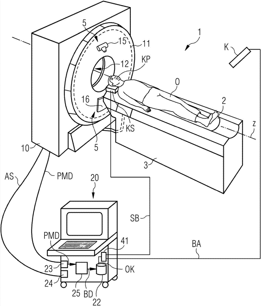
technical field [0001] The invention relates to a method for positioning an examination object for an imaging method. Furthermore, the invention relates to an object locating facility. Finally, the invention relates to an imaging medical facility. Background technique [0002] Modern imaging methods are frequently used to create two-dimensional or three-dimensional image data, which can be used to visualize the imaged examination object and additionally for further applications. [0003] Imaging methods are often based on the acquisition of x-rays, in which so-called projection scan data are produced. For example, projection scan data may be acquired by a computed tomography system (CT system). With a CT system, the combination of an X-ray source and an oppositely arranged X-ray detector, usually arranged on a gantry, rotates around a scanning room where an examination object (hereafter referred to as a patient without loss of generality) is located. In this case, the ce...

Claims


Application Information

Patent Timeline
IPC IPC(8): A61B6/03A61B5/055
CPCA61B6/03A61B6/04A61B5/055G01R33/283A61B5/70A61B5/0077A61B6/488A61B6/032A61B6/542A61B6/44A61B6/4208A61B6/589A61B6/4429A61B6/42A61B6/4435A61B6/4258A61B6/4441A61B6/54A61B6/035A61B6/0414A61B6/0407A61B6/48A61B6/544A61B6/545G01R33/30
Inventor D·莱尔希
Owner SIEMENS HEALTHCARE GMBH
Learn More