
Ore pulp thickener

A technology for thickeners and ore pulp, applied in the field of thickeners, can solve the problems of inconvenient use and maintenance, large floor area, easy to press rakes, etc., and achieve the effect of convenient maintenance and good effect.

Pending Publication Date: 2017-12-15
沧源县云矿金腊资源有限公司
View PDF7 Cites 5 Cited by
  • Summary
  • Abstract
  • Description
  • Claims
  • Application Information

AI Technical Summary

Problems solved by technology

However, there are defects such as large floor area occupied by traditional concentrators, poor solid-liquid separation effect, easy raking under load operation, and inconvenient use and maintenance.

Method used


Image

  • Ore pulp thickener
  • Ore pulp thickener

Examples


Embodiment Construction

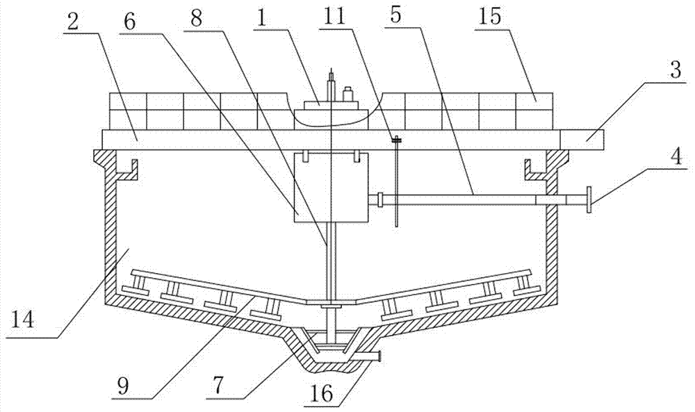
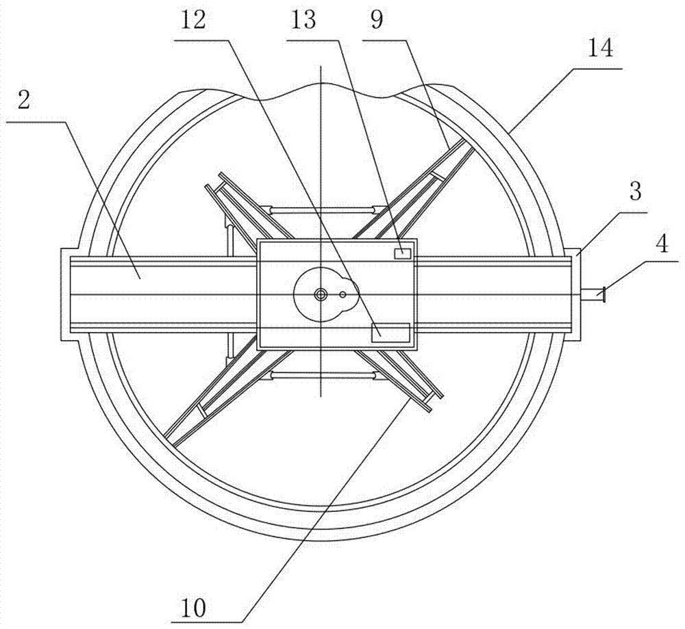
[0015] Such as Figure 1~2 As shown, a pulp thickener includes a thickening tank 14, and also includes a transmission device 1, a bridge frame 2, a ladder 3, a feed port 4, a feed pipe 5, a fixed cylinder 6, a scraper 7, a shaft 8, and a drive shaft rake , boom 11, hydraulic station 12, electric control device 13, conveying pipe 16, the bridge frame 2 is arranged on the top of the concentration pool 14, the transmission device 1 is arranged on the bridge frame 2, the ladder 3 is connected with the bridge frame 2, and the The feed port 4 is arranged on one side of the concentration tank 14, the feed pipe 5 is arranged in the concentration tank 14, and the two ends of the feed pipe 5 are respectively connected with the feed port 4 and the fixed cylinder 6, and the fixed cylinder 6 is set Below the bridge frame 2, the shaft 8 is set in the concentration tank 14 and connected to the transmission device 1, the scraper 7 is set at the center of the bottom of the concentration tank 1...


PUM


Abstract

The invention relates to an ore pulp thickener which comprises a thickening tank and further comprises a transmission device, a bridge, a ladder, a feeding hole, a feed pipe, a fixed cylinder, a scraper, a shaft, a transmission shaft rake, a lifting rod, a hydraulic pressure station, an electric control device and a delivery pipe, wherein the bridge is arranged on the top of the thickening tank; the transmission device is arranged on the bridge; the ladder is connected with the bridge; the feeding hole is formed in one side of the thickening tank; the feed pipe is arranged in the thickening tank; two ends of the feed pipe are respectively connected with the feeding hole and the fixed cylinder; the fixed cylinder is arranged below the bridge; the shaft is arranged in the thickening tank and connected with the transmission device; the scraper is arranged in the center at the bottom of the thickening tank; the transmission shaft rake is connected with the shaft; the lifting rod is arranged on the bridge; the hydraulic pressure station and the electric control device are arranged on the bridge; and the delivery pipe is arranged at the bottom of the thickening tank. The thickener is simple in structure, convenient to use and maintain and excellent in clarifying and thickening effects.

Description

technical field [0001] The invention relates to a thickener, in particular to a pulp thickener. Background technique [0002] The traditional concentrator consists of a shell, a driving device and a rake scraper. The solid particles suspended in the slurry in the thickening tank settle under the action of natural gravity, and the upper part becomes clarified water to separate the solid and liquid. The slime deposited at the bottom of the thickening tank is continuously scraped and collected by the rake scraper to the discharge port at the center of the bottom of the tank, while the clarified water overflows from the upper edge of the thickening tank. However, there are defects such as the traditional concentrator occupies a large floor area, has poor solid-liquid separation effect, is easy to be crushed during load operation, and is inconvenient to use and maintain. Contents of the invention [0003] The purpose of the present invention is to provide a high-efficiency co...

Claims


Application Information

Patent Timeline
Patent Type & Authority Applications(China)
IPC IPC(8): B01D21/06B01D21/18
CPCB01D21/06B01D21/18
Inventor 邹贵阳黄波孙学宇
Owner 沧源县云矿金腊资源有限公司
Learn More