Swinging material retreating device

A technology of returning material and driving rod, which is applied in the field of vehicle parts processing to achieve the effect of improving production efficiency and reducing the difficulty of production operations

Inactive Publication Date: 2017-12-15
ANHUI JIANGHUAI AUTOMOBILE GRP CORP LTD
View PDF4 Cites 1 Cited by
  • Summary
  • Abstract
  • Description
  • Claims
  • Application Information

AI Technical Summary

Problems solved by technology

[0004] The purpose of the present invention is to provide a swinging material return device to solve the problems in the prior art, reduce the difficulty of operation, and greatly improve the production efficiency

Method used


Image

  • Swinging material retreating device
  • Swinging material retreating device
  • Swinging material retreating device

Examples


Embodiment Construction

[0026] Embodiments of the present invention are described in detail below, examples of which are shown in the drawings, wherein the same or similar reference numerals designate the same or similar elements or elements having the same or similar functions throughout. The embodiments described below by referring to the figures are exemplary only for explaining the present invention and should not be construed as limiting the present invention.

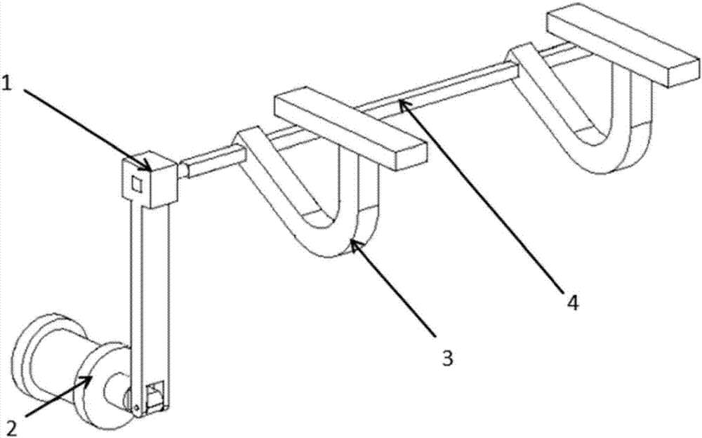
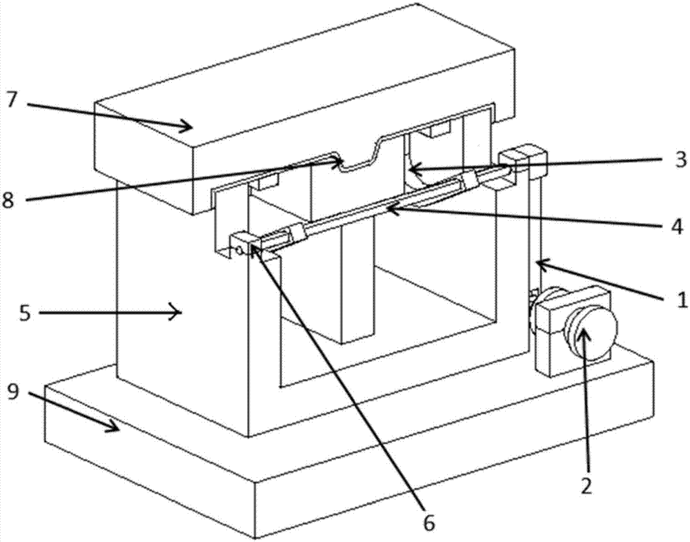
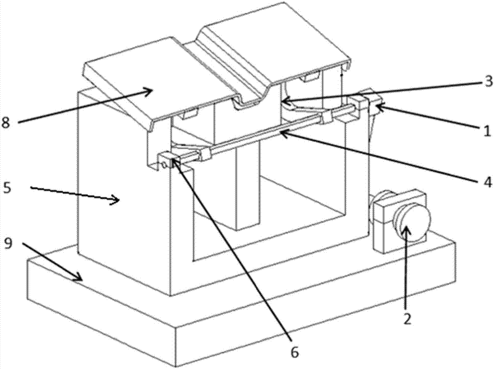
[0027] Such as figure 1 shown, see also figure 2 with image 3 , the present invention provides a swing stripping device, the swing stripping device includes: a driving structure 2, a transmission rod 1, a rotating shaft 4, a rocker arm 3, a base 9, an upper mold 7 and a lower mold 5, and the lower mold 5 Both the driving structure 2 and the driving structure 2 are arranged on the base 9, the workpiece 8 is placed on the lower mold 5, the upper mold 7 is buckled on the workpiece 8, the rotating shaft 4 is set on the lower mold 5, and ...


PUM


Abstract

The invention discloses a oscillating unloading device, comprising: a driving structure, a transmission rod, a rotating shaft, a rocker arm, a base, an upper mold and a lower mold, and the driving structure drives the second end of the transmission rod to move relative to the first end of the transmission rod, That is, the first end of the transmission rod can be rotated, so that the rotating shaft and the rocker arm can be driven to rotate together, so that the second end of the rocker arm supports the workpiece from the bottom of the workpiece. Since the rocker arm rotates with the rotating shaft, the movement track of the rocker arm is arc shape, the workpiece can be pushed out at a certain angle close to the operator, and the operator can simply and conveniently complete the material removal; and because the driving structure is placed outside the lower mold, it is not limited by the inner space of the lower mold; therefore, the present invention It can reduce the difficulty of production operation and greatly improve production efficiency.

Description

technical field [0001] The invention relates to the field of vehicle parts processing, in particular to a swinging material-removing device. Background technique [0002] With the continuous development of the automobile manufacturing industry. The speed of model replacement is getting faster and faster, and the production convenience of body panels will directly affect production efficiency. In the production process of stamping parts, many parts are difficult to pick up. [0003] Under the existing technical conditions, a jacking cylinder is used in the middle of the mold, and the jacking cylinder directly ejects the upper plate, but when taking the plate, the operator still needs to lift it up first, and then move the plate down and carry it It is extremely inconvenient; and due to the limitation of many mold spaces, the jacking cylinder cannot be placed, and the finished plate can only be picked up manually, which reduces production efficiency and increases the difficu...

Claims


Application Information

Patent Timeline
Patent Type & Authority Applications(China)
IPC IPC(8): B21D45/04
CPCB21D45/04
Inventor 高双明张强胡晓妍王亚龙李辉戴冬华
Owner ANHUI JIANGHUAI AUTOMOBILE GRP CORP LTD
Why Eureka
Try Eureka