
Plugging device

A sealing device and sealing plate technology, applied in the field of mechanical components, can solve the problems of no protective device, easy blocking of operators, poor sealing effect, etc., and achieve easy operation, good sealing structure and simple structure Effect

Inactive Publication Date: 2017-12-15
DONGGUAN ZHIPEI ELECTROMECHANICAL TECH CO LTD
View PDF0 Cites 0 Cited by
  • Summary
  • Abstract
  • Description
  • Claims
  • Application Information

AI Technical Summary

Problems solved by technology

[0002] In the process of steelmaking, the water outlet needs to be blocked in time after the molten iron flows out through the water outlet. The general sealing method is to use iron rods for sealing, and the direct sealing method is adopted. There is no protective device on the iron rods. Molten iron is easy to splash when personnel operate, and the risk factor is high
In order to address this shortcoming, a steelmaking water outlet sealing device that can effectively block the splashing of molten iron was designed later. A sleeve rod is set in the device, and a bracket is provided on the sleeve rod. There is a baffle fixed by a buckle near the end of the bracket. Although the baffle can protect the operator to a certain extent, the baffle is easy to block the operator's sight and cause poor sealing effect. Therefore, it needs to be improved. Design a blocking device that can play a good blocking effect without blocking the operator's sight and is easy to operate

Method used


Image

  • Plugging device

Examples


Embodiment Construction

[0018] The present invention is described in further detail now in conjunction with accompanying drawing. These drawings are all simplified schematic diagrams, which only illustrate the basic structure of the present invention in a schematic manner, so they only show the configurations related to the present invention.

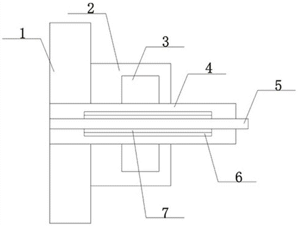
[0019] Such as figure 1 The preferred embodiment of the sealing device of the present invention shown includes a reinforced steel plate 1, a sealing plate 2 is installed on one side of the reinforced steel plate 1, the sealing plate 2 is fixedly connected with the reinforced steel plate 1, and the sealing plate 2 and the reinforced steel plate 1 are connected together. A baffle 4 is connected, and one end of the baffle 4 is fixed on the inner side of the reinforced steel plate 1, and the other end passes through the reinforced steel plate 1 and the sealing plate 2 to extend outside the sealing plate 2, and a sleeve rod 5 is installed inside the baffle 4, and t...


PUM


Abstract

The invention discloses a plugging device, which comprises a reinforced steel plate. A sealing plate is installed on one side of the reinforced steel plate. The sealing plate is fixedly connected to the reinforced steel plate. A baffle is connected between the sealing plate and the reinforced steel plate. On the inner side of the reinforced steel plate, the other end passes through the reinforced steel plate and the sealing plate and extends outside the sealing plate. A sleeve rod is installed inside the baffle, and one end of the sleeve rod extends outside the baffle. The sleeve rod adopts a hollow structure, and the sleeve rod is covered with Covered with a sealing plate, the sealing plate is fixedly connected with the sleeve rod, and the outer side of the sealing plate is equipped with a vertebral body plug, which is on the same horizontal line as the end of the sealing plate, and also includes an iron sheet, which is vertically arranged on the sealing plate Inside, the two ends of the iron sheet pass through the sleeve rod, the sealing plate and the vertebral body plug respectively. The sealing device has good sealing structure, is simple in structure, is easy to operate, can avoid damage to pipelines caused by deep welding depth, not only improves engineering quality, but also has high safety performance and is convenient for cleaning.

Description

technical field [0001] The invention relates to a mechanical component, in particular to a blocking device. Background technique [0002] In the process of steelmaking, the water outlet needs to be blocked in time after the molten iron flows out through the water outlet. The general sealing method is to use iron rods for sealing, and the direct sealing method is adopted. There is no protective device on the iron rods. Molten iron is easy to splash when personnel operate, and the risk factor is high. In order to address this shortcoming, a steelmaking water outlet sealing device that can effectively block the splashing of molten iron was designed later. A sleeve rod is set in the device, and a bracket is provided on the sleeve rod. There is a baffle fixed by a buckle near the end of the bracket. Although the baffle can protect the operator to a certain extent, the baffle is easy to block the operator's sight and cause poor sealing effect. Therefore, it needs to be improved. ...

Claims


Application Information

Patent Timeline
IPC IPC(8): C21C5/46F27D3/15
CPCC21C5/4653F27D3/1536
Inventor 李少军
Owner DONGGUAN ZHIPEI ELECTROMECHANICAL TECH CO LTD
Learn More