Device and method for sealing metal and glass

A technology for sealing glass and metal, which is applied in the field of metal and glass sealing devices, and can solve problems such as difficult sealing, difficult glass sealing, and easy deformation

Active Publication Date: 2013-06-12
INST OF ELECTRICAL ENG CHINESE ACAD OF SCI
View PDF5 Cites 16 Cited by
  • Summary
  • Abstract
  • Description
  • Claims
  • Application Information

AI Technical Summary

Problems solved by technology

For example, the U.S. Patent US6324870 proposes a kind of high borosilicate glass (Pyrex glass) with an expansion coefficient of 17×10 -6 /K stainless steel for non-matching sealing method, the stainless steel with high expansion coefficient is processed into a very thin tip (less than 0.1mm), and then heated on a glass lathe for heat fusion sealing with high borosilicate glass, through the thin wall The elastic-plastic deformation of stainless steel relieves the thermal stress after sealing, but this technology requires glass operators to have a higher technical level and operating experience, first burn the glass on the outer wall of the metal, and then burn the inner wall, but in the operation Because the metal is too thin, it is easy to deform and wrinkle at high temperature, and it is difficult to form a good seal
[0005] CN10

Method used


Image

  • Device and method for sealing metal and glass
  • Device and method for sealing metal and glass
  • Device and method for sealing metal and glass

Examples


Embodiment 1

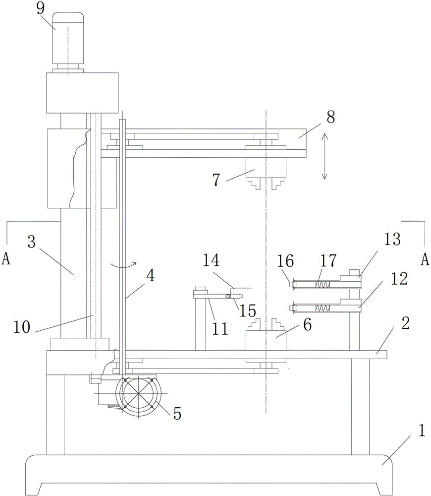
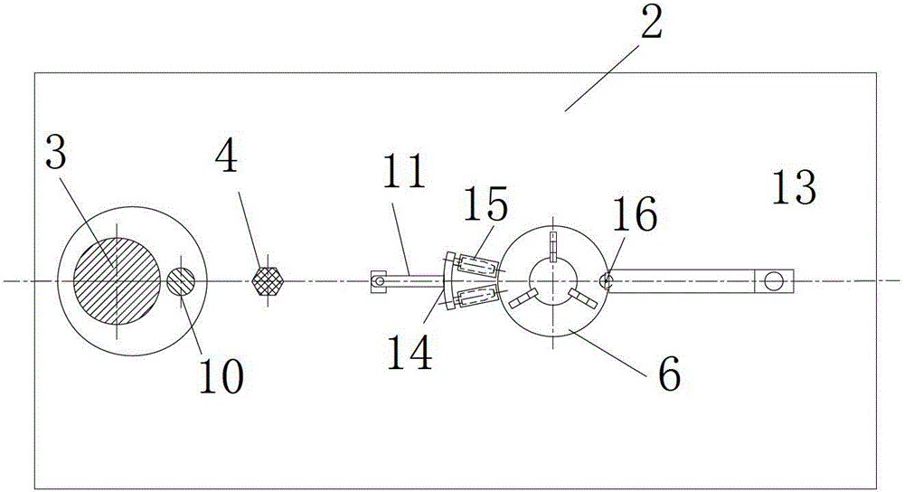
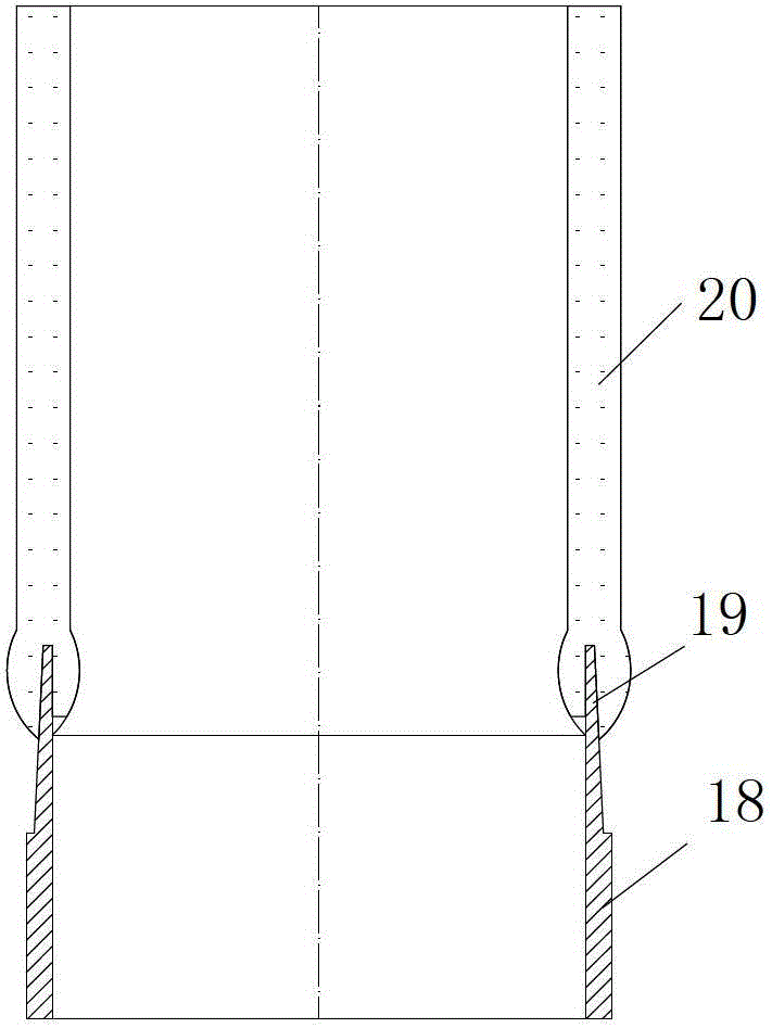
[0030] In this embodiment, the glass and metal sealing method is as follows: first, the sealing area of ​​the metal ring 18 with an inner diameter of 116 mm and a wall thickness of 1 mm is pre-processed into a thin-walled knife edge 19 with a length of 15 mm, and the top wall thickness of the thin-walled knife edge 19 is 0.03. mm, with a taper of 1°, and then fix the metal ring 18 on the lower fixture 6. Fix the glass tube 20 with a diameter of 120 mm and a wall thickness of 3 mm on the upper fixture 7 . Turn on the upper motor drive device 9, and move the positioning device 8 through the screw 10 to move the glass tube 20 down along the column 3 to make contact with the metal ring 18; open the lower motor drive device 5 to synchronize the glass tube 20 with the metal ring 18 , Coaxial rotation, the speed is 20 rpm. Turn on the heating burner 11 with 6 nozzles 15 to start preheating, control the temperature of the glass tube 20 to 500°C, and adjust the distance between the up...

Embodiment 2

[0032] The sealing method between glass and metal in this embodiment is as follows: first, a metal ring 18 with an inner diameter of 96 mm and a wall thickness of 0.8 mm is fixed on the lower fixture 6; a glass tube 20 with an outer diameter of 100 mm and a wall thickness of 2.5 mm is fixed on the upper Fixture 7 on. Turn on the upper motor drive device 9, and move the positioning device 8 along the column 3 to move the glass tube 20 downwards to contact and align with the metal ring 18 through the screw 10. Open the lower motor driving device 5, and the glass tube 20 and the metal ring 18 are rotated synchronously and coaxially at a speed of 80 rpm. Turn on the heating torch 11 with two nozzles 15 to start preheating, control the temperature of the glass tube 20 to 300°C, and simultaneously adjust the distance between the upper coaxial positioning device 13 and the lower coaxial positioning device 12 to be controlled at 15mm, and the upper and lower coaxial The rotating whee...


PUM


Abstract

The invention relates to a device and method for sealing metal and glass. The device comprises a base (1), a working platform (2), an upright column (3), a screw rod (10), a synchronous rotating shaft (4), an upper clamp (7), a lower clamp (6), an upper coaxial positioning device (13), a lower coaxial positioning device (12), a movable positioning device (8), a heating fire head (11), an upper motor driving device (9) and a lower motor driving device (5), wherein the movable positioning device (8) moves up and down along the upright column (3) for positioning to control the upper clamp (7) which clamps a glass tube to move in a vertical direction and be positioned; the upper clamp (7) and the lower clamp (6) can synchronously and coaxially rotate; the upper coaxial positioning device (13) and the lower coaxial positioning device (12) are provided with a spring retractable device (17) and a rotating wheel (16); and the heating fire head (11) is provided with at least two spray nozzles which are annularly arranged. According to the method for sealing the metal and the glass, soften glass can be fast subjected to double-surface sealing on a metal wall surface by utilizing the gravity action of the soften glass.

Description

technical field [0001] The invention relates to a metal-glass sealing device and a sealing method for high-temperature solar vacuum heat collecting tubes. Background technique [0002] High-temperature solar vacuum heat collector tubes are generally used in trough solar thermal power generation systems. The incident light is focused on the heat collector tube through a parabolic reflector that can track the sun. The heat collector tube absorbs sunlight to heat the working medium in the tube, thereby generating high-temperature steam. High-temperature solar vacuum heat collectors generally include a metal inner tube with a selective radiation-absorbing coating and a glass tube surrounding the metal inner tube. Due to the different expansion coefficients and different operating temperatures between the glass tube and the metal inner tube, the glass tube and the metal tube The difference in axial expansion between the inner tubes is alleviated by bellows located at both ends. ...

Claims


Application Information

Patent Timeline
IPC IPC(8): C03C27/02
Inventor 雷东强王志峰张剑寒白凤武
Owner INST OF ELECTRICAL ENG CHINESE ACAD OF SCI
Why Eureka
Try Eureka