Yarn pressing device of computer flat-knitting machine

A flat knitting machine and yarn pressing technology, applied in the directions of knitting, weft knitting, textiles and paper making, etc., can solve the problems of unseen, floating yarn and scrapping, etc., and achieve the effect of ensuring the quality of knitting

Active Publication Date: 2017-12-15
JIANGSU JINLONG TECHNOLOGY CO LTD
View PDF10 Cites 0 Cited by
  • Summary
  • Abstract
  • Description
  • Claims
  • Application Information

AI Technical Summary

Problems solved by technology

[0003] However, in the process of weaving metal fiber fabrics on a computerized flat knitting machine, the following confusions are often encountered: when the yarn feeder feeds the yarn, the metal fiber yarn bulges and floats upward, which affects the knitting needle hook to take the yarn and Loops will eventually affect the quality of the fabric and even cause scrapping, and the faster the weaving speed, the more serious the yarn floats
Aiming at this technical problem, the applicant has searched the literature, but there is no beneficial enlightenment to solve this technical problem in Chinese and foreign patents and non-patent literature. The technical solution to be introduced below is produced under this background

Method used


Image

  • Yarn pressing device of computer flat-knitting machine

Examples


Embodiment Construction

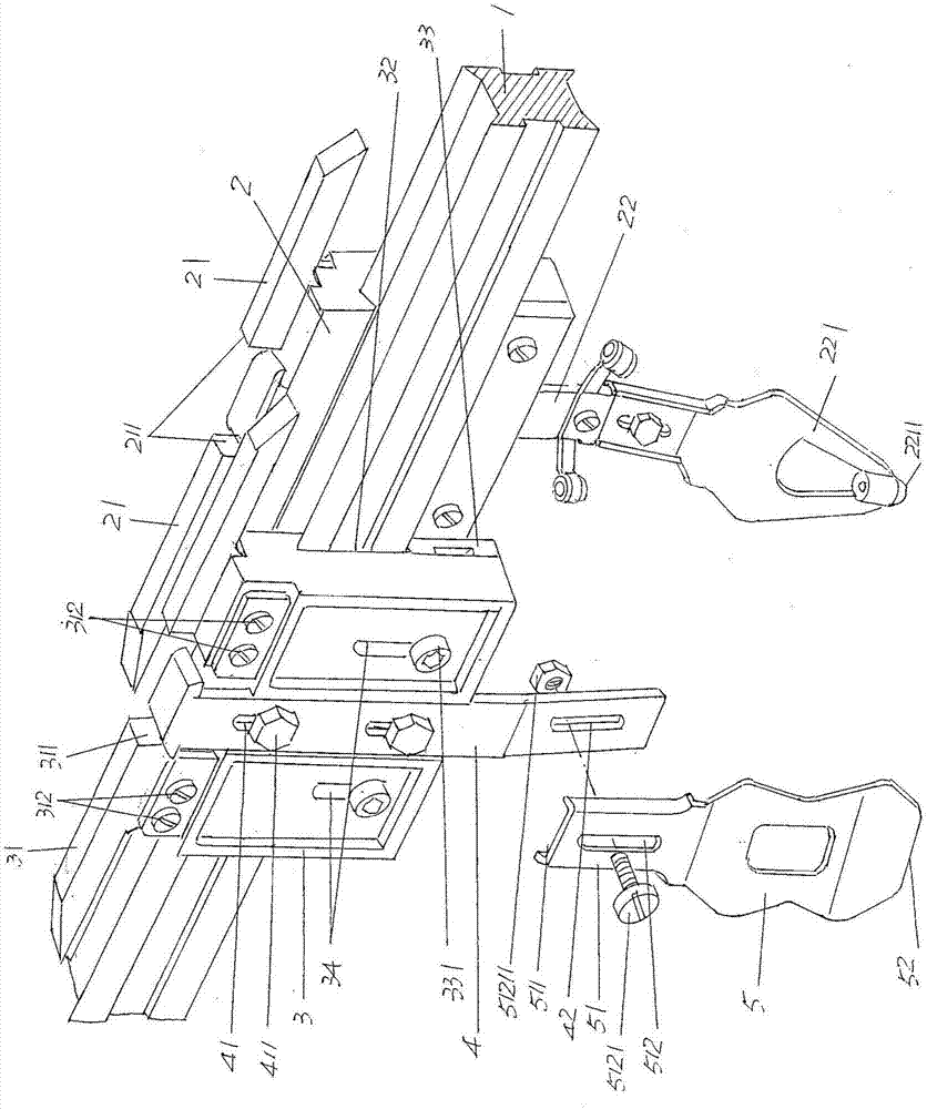
[0017] See figure 1 , shows the guide rail 1 (also called "yarn feeder guide rail") of the structural system of the computerized flat knitting machine and the yarn feeder seat 2 arranged on the guide rail 1 to move left and right, and a pair of yarn feeder seats 2 are fixed on the upper part The yarn feeder seat contact feet 21 with opposite directions to each other, the space between the pair of yarn feeder seat contact feet 21 constitutes a shuttle changing slider cavity 211, and there is a yarn feeding feeder guide rod 22 at the bottom of the yarn feeder seat 2. A yarn feeding feeder 221 is fixed at the bottom of the yarn feeder guide rod 22 . Since this structure of the computerized flat knitting machine belongs to the known technology, for example, please refer to CN201305729Y (yarn feeder seat), so the applicant will not repeat it here.

[0018] As the technical points of the technical solution provided by the present invention: the yarn pressing device provided by the ...


PUM


Abstract

The invention provides a yarn pressing device of a computer flat-knitting machine. The computer flat-knitting machine includes a guide rail and a yarn nozzle base, wherein the yarn nozzle base is arranged on the guide rail in a left-and-right moving mode; the upper portion of the yarn nozzle base is fixedly provided with a pair of yarn nozzle base palping feet different in direction, the space between the pair of yarn nozzle base palping feet is configured into a shuttle changing sliding block cavity, the lower portion of the yarn nozzle base is provided with a yarn feeding nozzle guide rod, the lower portion of the yarn feeding nozzle guide rod is provided with a yarn feeding nozzle, and the yarn pressing device includes a yarn pressing plate base, a yarn pressing tongue plate fixing rod and a yarn pressing tongue plate; a yarn pressing tongue plate base is cooperated with the guide rail at the position corresponding to the front side of the yarn nozzle base in a sliding mode, the upper portion of the yarn pressing tongue plate base is fixedly provided with a pair of yarn pressing tongue plate base palping feet different in direction, the space between the pair of yarn pressing tongue plate base palping feet is configured into a direction-change block cooperation cavity, the upper end of the yarn pressing tongue plate fixing rod is fixed with the middle position of the side, back on to the guide rail, of the yarn pressing tongue plate base, the lower end of the yarn pressing tongue plate fixing rod stretches to the lower portion of the yarn pressing tongue plate base, and the yarn pressing tongue plate is fixed to the lower end of the yarn pressing tongue plate fixing rod. The weaving quality of a metal fiber fabric is ensured.

Description

technical field [0001] The invention belongs to the technical field of computerized flat knitting machines, and in particular relates to a yarn pressing device of a computerized flat knitting machine. Background technique [0002] As known in the textile industry, because metal fibers have unique properties and wide applications like organic and inorganic fibers, specifically, metal fibers have good electrical conductivity, thermal conductivity, magnetic conductivity and high temperature resistance, so metal fiber fabrics such as anti- Radiation fabrics, anti-electromagnetic fabrics, fireproof fabrics, etc. are deeply favored by people. Implanting high-tech brushed metal fibers into fabrics can form high-grade fabrics with good added value. Metal fiber textile fabrics are usually mainly polyester-cotton, nylon-cotton, nylon-polyester, and cotton metal fiber fabrics, and the mass percentage of metal fibers usually accounts for about 3-8% of the total weight of the fabric. ,...

Claims


Application Information

Patent Timeline
Patent Type & Authority Applications(China)
IPC IPC(8): D04B15/56
CPCD04B15/565
Inventor 金永良贾健钱新华徐备松黄健飞
Owner JIANGSU JINLONG TECHNOLOGY CO LTD
Why Eureka
Try Eureka