Floor tile paving device and method

A technology for floor tiles and ceramic tiles, which is applied in the field of equipment for helping floor tiles to be laid flat, can solve problems such as insufficient laying efficiency, high flatness requirements, and poor laying effects, and achieves improved laying efficiency and good aesthetics. Effect

Inactive Publication Date: 2017-12-15
CHENGDU NENGGAO GONGJIAN NEW ENVIRONMENTAL PROTECTION BUILDING MATERIAL CO LTD
8 Cites 2 Cited by

AI-Extracted Technical Summary

Problems solved by technology

[0004] (1) The existing tile bonding method is to apply a layer of adhesive on the base layer, and then lay the ground drill on it. This method of laying has high requirements for the flatness of the base layer. If the flatness of the base layer is not good It cannot be used, because it ...

Method used

The main pulley is one-time vertically sliding on a row of tiles, and the toothed hanging board can comb a row of glue, so that when...

Abstract

The invention discloses a floor tile paving device. According to the floor tile paving device, the problems that in the prior art, paving is not level, hollowing is prone to generating, and the paving efficiency is low are solved. The floor tile paving device comprises a rack; the two ends of the rack are provided with a main pulley for sliding on a tile and an auxiliary pulley for sliding on a base layer correspondingly; tooth-shaped scraping plates are further arranged on the portion, between the main pulley and the auxiliary pulley, of the rack; horizontal instruments are arranged at the two ends of the top of the rack; and the height of the rack can be adjusted through the main pulley and the auxiliary pulley. Through the floor tile paving device, the problems in the prior art can be well solved.

Application Domain

Technology Topic

Image

  • Floor tile paving device and method

Examples

  • Experimental program(1)

Example Embodiment

[0029] Example
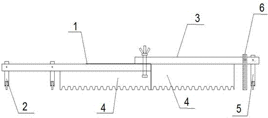
[0030] Such as figure 1 As shown, the floor tile applicator includes a frame. In order to adapt to the size of the floor tiles and facilitate adjustment of the specifications of the frame, the frame is composed of a first bracket 1 and a second bracket 3.
[0031] The bottom of one end of the first bracket is provided with two main pulleys 2 with a certain interval. The other end of the first bracket is a connecting end for connecting with the second bracket. The connecting end of the first bracket is provided with a plurality of connecting through holes arranged side by side. A toothed scraper 4 is also provided between the two ends of the first bracket. The toothed scraper and the main pulley are both connected with the first bracket by bolts.
[0032] It needs to be specifically explained that in the vertical direction, the position of the main pulley relative to the first bracket can be changed. That is, the main pulley includes a pulley frame and a pulley body installed at the bottom of the pulley frame. The first bracket is provided with a through hole for the pulley bracket to pass through in the vertical direction, and the side of the first bracket is also provided with a threaded hole communicating with the above-mentioned through hole for screwing the bolt through the first bracket to block the pulley bracket, thereby The relative position between the pulley and the first bracket can be adjusted, thereby adjusting the height of the first bracket.
[0033] One end of the second bracket is a connecting end, and the other end is provided with an auxiliary pulley 5. The connecting end of the second bracket is also provided with a plurality of connecting through holes arranged side by side. The connecting end of the first bracket is located below the connecting end of the second bracket, and the connecting through holes of the two are aligned and connected by bolts. A toothed scraper is also provided between the two ends of the second bracket.
[0034] The two ends of the top of the rack are also equipped with level meters.
[0035] On the second bracket, a mudguard 6 is also provided between the toothed scraper and the auxiliary pulley. The mudguard is arranged on the second bracket through a sliding assembly. The sliding assembly includes a vertical sliding groove and a sliding block bolt arranged on the fender. The sliding block bolt passes through the vertical sliding groove and is fixed on the second bracket. The sliding assembly makes the position between the mudguard and the second bracket self-adjustable. The mudguard is an L-shaped plate, so that one surface of the L-shaped plate is provided with a vertical slide groove, which is connected to the second bracket, and the other surface is perpendicular to the second bracket for scraping off excess glue .
[0036] The local brick paving tool is used to comb the glue.
[0037] The principle of use of this embodiment is as follows:
[0038] The main pulley is placed on the already laid tiles, the secondary pulley is placed on the base layer, and the toothed scraper combs the glue on the base layer. The level gauges at both ends of the rack can detect the level of the rack. If the rack is not level, adjust the height of the rack by adjusting the secondary pulley to ensure that the rack is level.
[0039] The main pulley slides vertically on the tiles to press the floor tiles and at the same time play a height standard role. When sliding, once the bracket is not level, adjust it with the auxiliary pulley. At this time, the height of the toothed scraper is maintained, so that the total height of the base layer and the glue layer is fixed, so that the tiles laid on the glue are very flat.
[0040] The main pulley slides vertically on a row of tiles at a time, and the toothed hanging board can comb a row of glue, so that when paving, another row of paving can be realized, which can realize fast paving and greatly improve work efficiency.
[0041] In this embodiment, the mudguard is connected to the second bracket through the sliding assembly, and the installation position of the bolts in the sliding assembly on the second bracket can be adjusted, so that the mudguard can be adjusted to just the edge according to the size of the floor tiles The size of the glue can be separated and scraped away for subsequent use. And the bolts of the slider used on the fender can slide on the chute, so that the fender can be adjusted up and down autonomously following the terrain.
[0042] With the equipment of this embodiment, it is possible to facilitate leveling during floor tile paving, uniform combing of the toothed scraper, to prevent hollowing, and to improve the paving efficiency.

PUM

no PUM

Description & Claims & Application Information

We can also present the details of the Description, Claims and Application information to help users get a comprehensive understanding of the technical details of the patent, such as background art, summary of invention, brief description of drawings, description of embodiments, and other original content. On the other hand, users can also determine the specific scope of protection of the technology through the list of claims; as well as understand the changes in the life cycle of the technology with the presentation of the patent timeline. Login to view more.

Similar technology patents

Embedded-bead type door handle

Owner:JIANGYIN TONGQI HARDWARE ELECTRICAL APPLIANCE FACTORY

Classification and recommendation of technical efficacy words

  • Improve laying efficiency
  • Good aesthetics

Five-freedom-degree rapid forming processing apparatus

InactiveCN104842557AEliminate the step effectImprove laying efficiencyAdditive manufacturing apparatusForm processingForms processing
Owner:CHINA UNIV OF MINING & TECH

Cup holder

Owner:SHANGHAI NIFCO PLASTIC MANUFACTURER CO LTD
Why Eureka
Try Eureka