Electronic coded lock

An electronic combination lock and unlocking technology, applied in the field of lock equipment, can solve the problems of waste of production cost of electronic locks, increase of management and maintenance costs, compatible use, etc.

Inactive Publication Date: 2017-12-15
ZHEJIANG SUNON FURNITURE MFG
View PDF7 Cites 2 Cited by
  • Summary
  • Abstract
  • Description
  • Claims
  • Application Information

AI Technical Summary

Problems solved by technology

[0003] Ordinary electronic locks have a single scope of use, either for steel cabinets or for wooden cabinets, and they cannot be used compatible, and a lock can only use one locking method: the above-mentioned locking method or the paddle, or the shifter , or rotating shaft, etc., so traditional electronic locks can only choose one locking method, so it is suitable for a specific type of cabinet installation
[0004] Therefore, the traditional electronic combination lock has a single range of fu

Method used


Image

  • Electronic coded lock
  • Electronic coded lock
  • Electronic coded lock

Examples


Embodiment 1

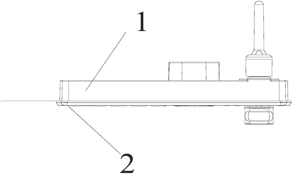
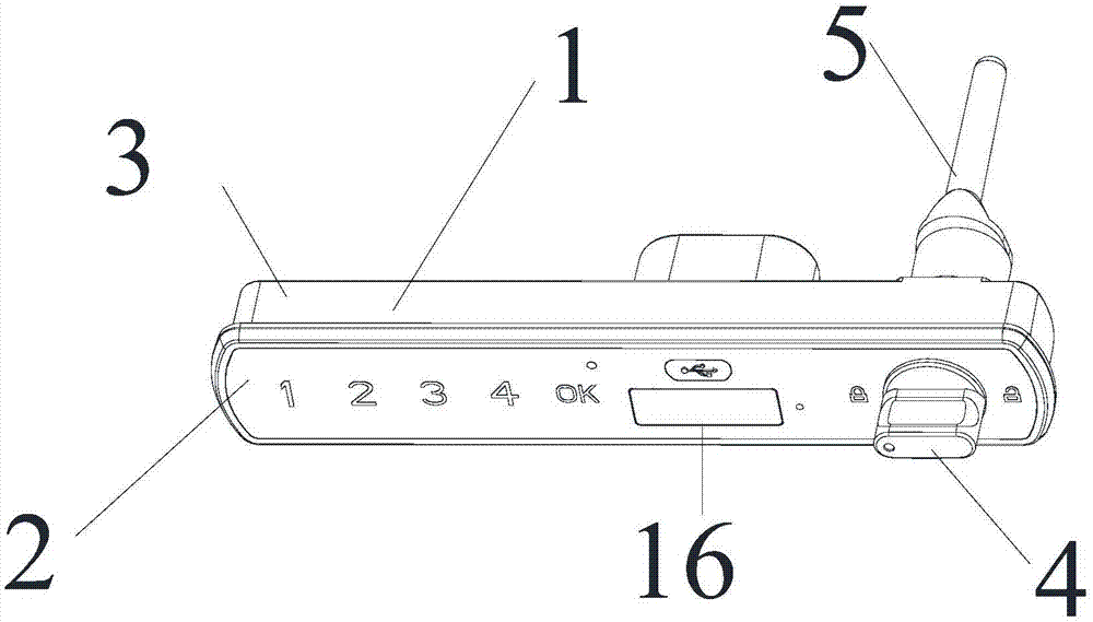
[0076] See 1, figure 2 , image 3 , (see especially Figure 4 , Figure 5, Image 6 The illustrated rotary shaft lock) Embodiment 1 of the present invention provides an electronic combination lock, and the present invention provides an electronic combination lock, including a main body device 1 and a panel device 2;

[0077] The main device 1 includes an inner shell 3, a knob 4 and a locking mechanism 5; the knob 4 is arranged outside the inner shell 3, and the locking mechanism 5 is arranged inside the inner shell 3; the The knob 4 is used to drive the locking mechanism 5 to rotate and cooperate to realize the manual unlocking action and the manual locking action of the electronic combination lockset;

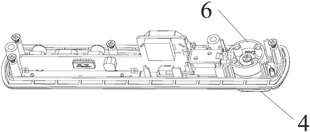
[0078] The locking mechanism 5 includes a cam mechanism 6, a first connecting sleeve 7, a rotating shaft 8 and a screw 9; wherein, the cam mechanism 6 includes a circular housing 10, and a plurality of positioning holes arranged inside the circular housing 10 11. The cam...

Embodiment 2

[0085] see Figure 9 , Figure 10 , Figure 11 The illustrated paddle type lock, correspondingly, the present invention provides an electronic password lock, including a main body device 1 and a panel device 2;

[0086] The main device 1 includes an inner shell 3, a knob 4 and a locking mechanism 5; the knob 4 is arranged outside the inner shell 3, and the locking mechanism 5 is arranged inside the inner shell 3; the The knob 4 is used to drive the locking mechanism 5 to rotate and cooperate to realize the manual unlocking action and the manual locking action of the electronic combination lockset;

[0087] The locking mechanism 5 includes a cam mechanism 6, a second connecting sleeve 22, a plectrum 23 and a screw 9; wherein, the cam mechanism 6 includes a circular housing 10, and a plurality of positioning positions arranged inside the circular housing 10 Holes 11; the cam mechanism 6 is fixedly connected to the knob 4; the knob 4 is used to drive the cam mechanism 6 to ach...

Embodiment 3

[0101] see Figure 12 , Figure 13 , Figure 14 The illustrated paddle type lock, correspondingly, the present invention provides an electronic password lock, including a main body device 1 and a panel device 2;

[0102] The main device 1 includes an inner shell 3, a knob 4 and a locking mechanism 5; the knob 4 is arranged on the outside of the inner shell 3, and the locking mechanism 5 is arranged on the inside of the inner shell 3; The knob 4 is used to drive the locking mechanism 5 to rotate and cooperate to realize the manual unlocking action and the manual locking action of the electronic combination lockset;

[0103] The locking mechanism 5 includes a cam mechanism 6, a seat cover 25, a third connecting sleeve 26 and a shift piece 27; wherein, the cam mechanism 6 includes a circular housing 10, and a plurality of Positioning holes 11; the cam mechanism 6 is fixedly connected with the knob 4 (specifically, fixedly connected by screws); the knob 4 is used to drive the c...


PUM


Abstract

The invention discloses an electronic coded lock comprising a body device and a panel device. The body device comprises an inner shell, a rotary knob and a locking mechanism. The rotary knob is arranged on the outer side of the inner shell. The locking mechanism is arranged on the inner side of the inner shell. The rotary knob is used for driving the locking mechanism to rotate, conduct cooperation and achieve manual unlocking action and manual locking action of the electronic coded lock. The locking mechanism is designed to be provided with three kinds of mechanism devices high in similarity. The electronic coded lock guarantees that most of parts can be compatibly used to the greatest extent; even if different styles of electronic locks are produced, it can be guaranteed that a large number of parts can be in common use; the electronic coded lock can be applied to steel cabinets and wooden cabinets and are suitable for multiple types of cabinets, and the electronic coded lock adopts the advanced touch key-press technology in the industry and the most energy-efficient power supply scheme.

Description

technical field [0001] The invention relates to the technical field of lock equipment, in particular to an electronic combination lock. Background technique [0002] As we all know, with the development of electronic locks, many furniture such as steel cabinets and wooden cabinets are equipped with electronic password locks; [0003] Ordinary electronic locks have a single scope of use, either for steel cabinets or for wooden cabinets, and they cannot be used compatible, and a lock can only use one locking method: the above-mentioned locking method or the paddle, or the shifter , or rotating shaft, etc., so traditional electronic locks can only choose one locking method, so it is suitable for a specific type of cabinet installation. [0004] Therefore, the traditional electronic combination lock has a single range of functions and cannot meet the various application environments of the cabinet, and there are almost no parts and components compatible with the electronic lock...

Claims


Application Information

Patent Timeline
IPC IPC(8): E05B47/00E05B49/00E05B9/00E05B17/22E05B15/00E05B63/00E05B65/52
CPCE05B9/002E05B15/00E05B17/22E05B47/00E05B49/00E05B63/0056E05B65/52E05B2047/0058
Inventor 倪良正张叙俊毛立武前春
Owner ZHEJIANG SUNON FURNITURE MFG
Why Eureka
Try Eureka