Bidirectional alignment laser centering adjustment device and centering method

A laser centering and adjusting device technology, which is applied in the direction of using optical devices, measuring devices, instruments, etc., can solve the problems of poor accuracy of centering results and cumbersome and complicated centering process

Active Publication Date: 2017-12-15
CHANGCHUN UNIV OF SCI & TECH
View PDF13 Cites 15 Cited by
  • Summary
  • Abstract
  • Description
  • Claims
  • Application Information

AI Technical Summary

Problems solved by technology

[0005] The invention provides a two-way alignment laser centering adjustment device and a centering method to solve the existing problems of poor centering result precision and relatively cumbersome and complicated centering process

Method used


Image

  • Bidirectional alignment laser centering adjustment device and centering method
  • Bidirectional alignment laser centering adjustment device and centering method
  • Bidirectional alignment laser centering adjustment device and centering method

Examples


Embodiment Construction

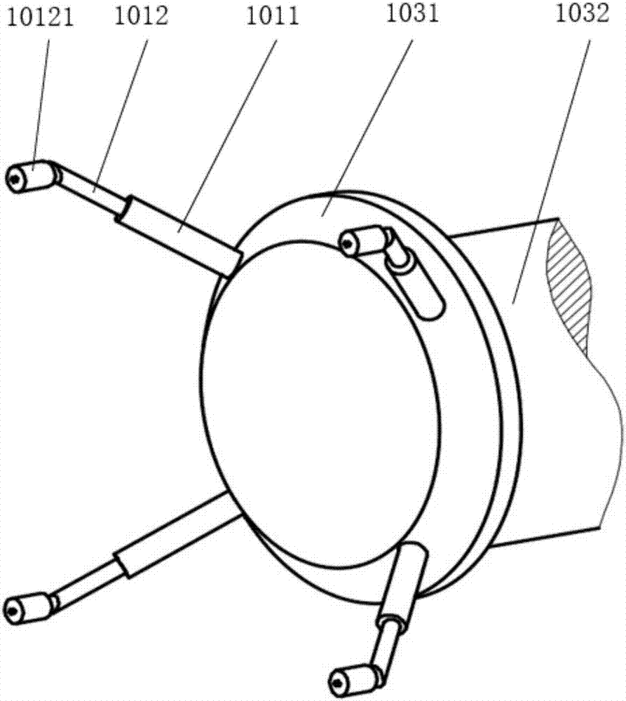
[0073] The two-way alignment laser centering adjustment device is composed of a fixed foot, a diameter measuring rear wing, a fixed laser receiving cylinder and a reversible laser macro and micro adjustment box, wherein the diameter measuring rear wing 102 is fixedly connected with the fixed laser receiving cylinder 103, and the fixed foot 101 is fixed on the fixed laser receiving tube 103, and the reversible laser macro-fine adjustment box 104 is fixedly connected with the fixed laser receiving tube 103.

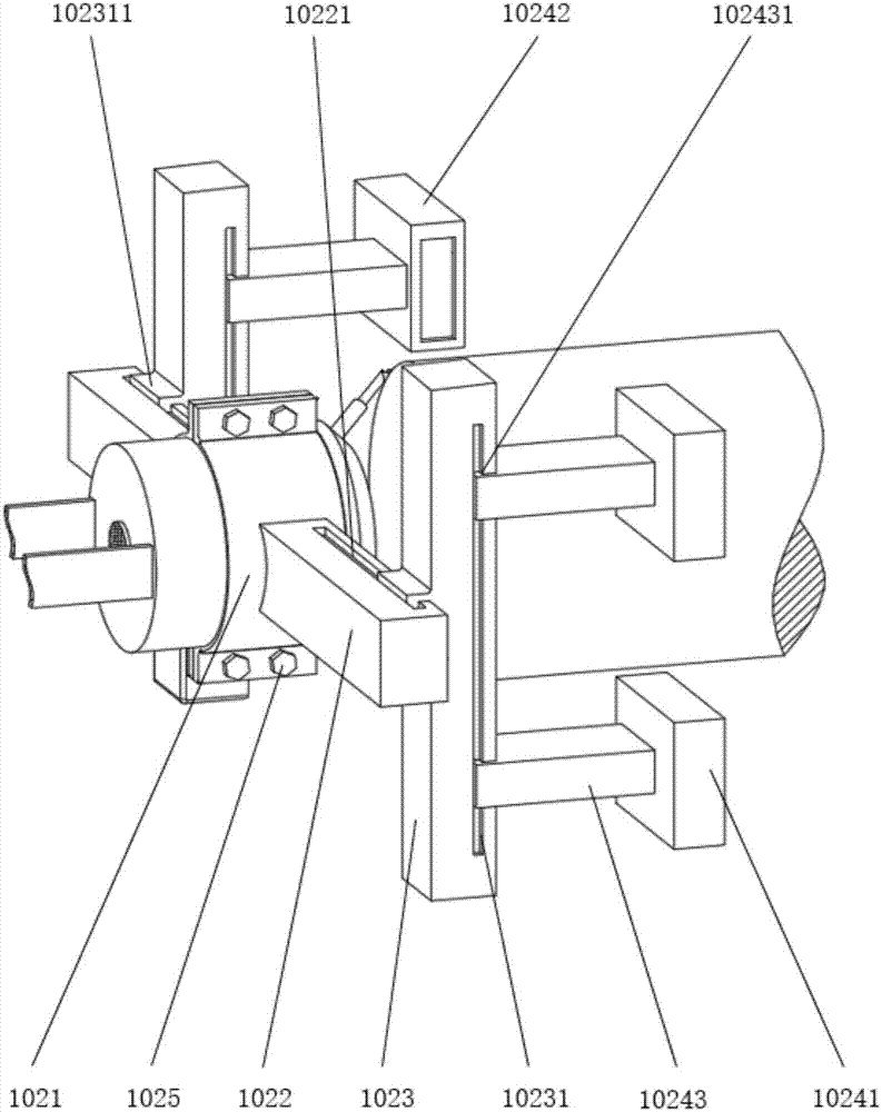
[0074] Such as figure 1 , figure 2 As shown, the fixed leg support 101 is composed of four fixed legs 1011 and four movable legs 1012; the diameter measuring rear wing 102 is connected with the fixed laser receiving cylinder 103 through the rotating shaft sleeve 1021, and is arranged on it The horizontal adjustment guide rail 1022 and the vertical adjustment guide rail 1023 adjust the high-precision CCD measurement receiver 1024, which can realize the diameter measurement...


PUM


Abstract

The invention relates to a bidirectional alignment laser centering adjustment device and a centering method, and belongs to the field of laser centering. A diameter measurement rear wing is fixedly connected with a fixed laser receiving cylinder, and a fixed leg support is fixed on the fixed laser receiving cylinder. A turnable laser macro-micro adjustment box is fixedly connected with the fixed laser receiving cylinder. The device is advantageous in that the device achieves the macro-micro adjustment of a laser, drives the laser to operate through the sticking-slipping inertia principle, obtains a laser linear equation through calculation, is used for a bidirectional centering shaft system, and enables the centering precision to be higher.

Description

technical field [0001] The invention relates to the field of laser centering, in particular to a high-precision laser centering device and method for centering shafts. Background technique [0002] In industrial production, the driving shaft is often used to drive the driven shaft to transmit torque and output power. As a key component for torque transmission and output power, the shaft system plays a very important role in the operation of the unit. The quality of the shafting alignment will directly affect the operation of the equipment, and at the same time, it is also a key indicator of the safety and service life of the equipment. For high-speed rotating shafting, high-precision alignment results can better reduce unit vibration, reduce friction and damage between equipment, and improve operating efficiency. [0003] In the existing shaft alignment methods, the dial indicator method is often used, but because of its complicated operation, large amount of manual calcula...

Claims


Application Information

Patent Timeline
Patent Type & Authority Applications(China)
IPC IPC(8): G01B11/27
CPCG01B11/27
Inventor 唐晨张茂云曹国华丁红昌
Owner CHANGCHUN UNIV OF SCI & TECH
Why Eureka
Try Eureka