Check patentability & draft patents in minutes with Patsnap Eureka AI!

Device and method for verifying monitoring precision of blind-spot monitoring system

A monitoring system and blind spot technology, applied in the field of monitoring accuracy devices, can solve the problems of troublesome operation, time-consuming, error-prone and other problems in the verification process

Pending Publication Date: 2017-12-15
GUANGQI HONDA
View PDF7 Cites 3 Cited by
  • Summary
  • Abstract
  • Description
  • Claims
  • Application Information

AI Technical Summary

Problems solved by technology

[0012] 1. The operation steps are complicated and time-consuming: multiple steps such as throwing a rope at the bottom of the vehicle, drawing an arc, and finding intersection points are required. Due to the many operation steps, it takes a long time and is error-prone;
[0013] 2. The auxiliary tools used are various and simple: scissors, stickers, ropes, and oil-based pens are required for the operation process. The preparation of auxiliary tools takes a long time and is inconvenient to use, which makes the operation of the verification process troublesome.
[0014] The difficulty of measuring the distance between AH and AF makes it difficult to verify the monitoring accuracy of the blind spot monitoring system. There is an urgent need for a method that can easily verify the monitoring accuracy of the blind spot monitoring system.

Method used


Image

  • Device and method for verifying monitoring precision of blind-spot monitoring system
  • Device and method for verifying monitoring precision of blind-spot monitoring system
  • Device and method for verifying monitoring precision of blind-spot monitoring system

Examples


Embodiment Construction

[0042] The specific implementation manners of the present invention will be further described in detail below in conjunction with the accompanying drawings and embodiments. The following examples are used to illustrate the present invention, but are not intended to limit the scope of the present invention.

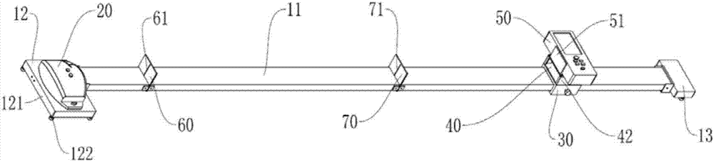
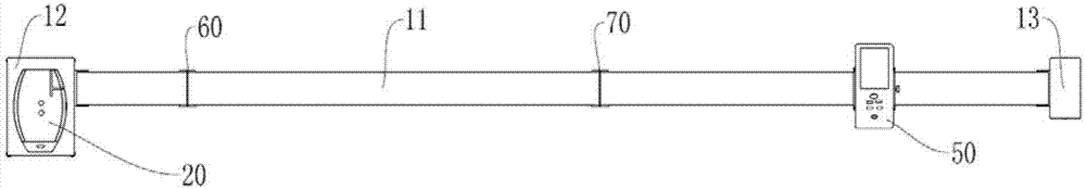
[0043] Such as figure 1 and figure 2 As shown, a device for verifying the monitoring accuracy of a blind spot monitoring system according to a preferred embodiment of the present invention includes a base 10, and the base 10 includes a linear guide rail 11 and first supports 12 respectively arranged at both ends of the linear guide rail 11 And the second support 13, the first support 12 is provided with a right-angle laser instrument 20 for emitting two vertical laser beams, the linear guide 11 is provided with a slider 30 that can slide along it, and the slide Reflector 40 and laser range finder 50 are installed on block 30, described reflector 40 comprises reflector ...


PUM


Abstract

The invention relates to the technical field of safety driving control technologies and disclosed a device and method for verifying the monitoring precision of a blind-spot monitoring system. The device comprises a linear guide rail, a first support and a second support, wherein the first support and the second support are arranged at the two ends of the linear guide rail respectively, the first support is provided with a right-angle laser instrument used for emitting two vertical laser beams, and a reflector and a laser range finder which can slide along the linear guide rail are arranged on the linear guide rail; by adjusting the position relation between the right-angle laser instrument and the reflector, the intersection point between a line which passes through a projection point, on a verification platform, of the middle point of a right rearview mirror camera and is parallel to the center line of an automobile and a line which passes through a projection point, on the verification platform, of the middle point of the tail portion of the automobile and is perpendicular to the center line of the automobile is determined; the distance between the intersection point and the projection point, on the verification platform, of the middle point of the right rearview mirror camera can be accurately measured through the laser range finder, so that the monitoring precision of the automobile blind-spot monitoring system is verified. Meanwhile, the invention further discloses the method for verifying the blind-spot monitoring system. Compared with a traditional verification method, the verification method is simple and accurate.

Description

technical field [0001] The invention relates to the technical field of safe driving control technology, in particular to a device and a verification method for verifying the monitoring accuracy of a blind spot monitoring system. Background technique [0002] In order to improve driving safety, many cars are currently equipped with a blind spot monitoring system (LWC). This function uses the camera in the right rearview mirror to capture images of the right rear of the vehicle and displays them on the screen of the center console. The relative distance between the object in the blind spot area and the vehicle displayed in , there are three target lines on the screen of the blind spot monitoring system: the first target line, the second target line, and the third target line, respectively marking the distance from the rear blind spot area to the rear of the vehicle is The reference position of L1, L2, L3 (3.15m, 11.2m, 24.0m), by installing the blind spot monitoring system on ...

Claims


Application Information

Patent Timeline
IPC IPC(8): G01S7/497
CPCG01S7/497Y02P90/30
Inventor 陈启波
Owner GUANGQI HONDA
Features
  • R&D
  • Intellectual Property
  • Life Sciences
  • Materials
  • Tech Scout
  • Unparalleled Data Quality
  • Higher Quality Content
  • 60% Fewer Hallucinations
Learn More