Bridge device

A technology of equipment and bridges, which is applied in the field of bridge equipment, can solve problems such as power outages of electrical equipment, difficult operation, and exposed electrical tanks, and achieve the effect of safe and stable power supply and increased use safety

Inactive Publication Date: 2017-12-15
俞备东
View PDF3 Cites 1 Cited by
  • Summary
  • Abstract
  • Description
  • Claims
  • Application Information

AI Technical Summary

Problems solved by technology

[0002] The construction and maintenance of bridges are inseparable from electrical equipment. The power supply of electrical equipment used for bridge construction and maintenance is basically to insert the plug arm connected to it directly into the power connection slot of the power inlet frame, and the power inlet frame and The mains connection will always be in the energized state. Although this matching method is relatively simple and convenient to operate, the length of the wires between the plug arm and the electrical equipment is different, and there is no other lock after the plug arm is inserted into the connection slot. The device locks the inserting arm. When the wire is accidentally kicked and bumped, the inserting arm will be separated from the electrical slot, resulting in a sudden power failure of the electrical equipment. In severe cases, it will directly cause damage to the electrical equipment. Therefore, there is an unstable power supply connection in the existing cooperation between the plug arm and the power connection slot. In addition, when the electrical equipment is not in use, the plug arm is often pulled out from the power connection slot, which will cause the connection The exposure of the electric tank poses a great safety hazard, and when the plug-in arm is pulled out from the electric tank, a large force needs to be exerted, which is not easy to operate

Method used


Image

  • Bridge device
  • Bridge device
  • Bridge device

Examples


Embodiment Construction

[0020] The preferred embodiments of the present invention will be described in detail below in conjunction with the accompanying drawings, so that the advantages and features of the present invention can be more easily understood by those skilled in the art, so as to define the protection scope of the present invention more clearly.

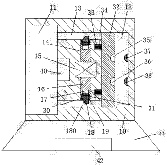
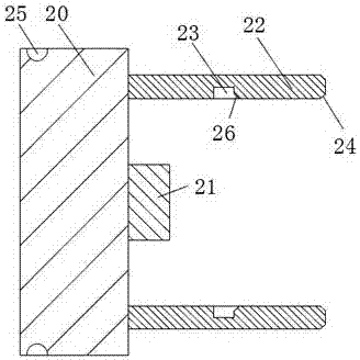
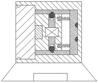
[0021] refer to Figure 1-5 The shown bridge equipment includes a power feed frame 10 and a power connection terminal 20 for mating connection with the power feed frame 10, and a plug arm 21 is arranged at the center of the right end face of the power connection terminal 20, and the On the right end surface of the connecting terminal 20, two socket boards 22 are provided on the front and rear sides of the socket arm 21, and a locking groove is provided on the inner end surface of each of the two socket boards 22. 23. A first hypotenuse 26 is provided on the inside of the right end of each of the two locking grooves 23, and a second hypotenuse 24 ...


PUM


Abstract

The invention discloses a bridge device, comprising an electric supply frame and an electric connection terminal in connection and cooperation with the electric supply frame. The center at the right end face of the electric connection terminal is provided with an insertion arm. The right end face of the electric connection terminal is provided with two insertion plates that are equally arranged at two sides of the front and the back of the insertion arm; each inner side end face of the two insertion plates is provided with a locking grove; and the inner side at each right end part of the two locking grooves is provided with a first inclined edge face; and the inner side at each right end face of the two insertion plates is provided with a second inclined edge face. The bridge device of the invention has a simple structure, and the supplied power is highly stable. Therefore, the power using safety in bridge construction can be increased, which ensures the life safety of people. In addition, as the unlocking of the electrical connection terminal is realized through a motor, it is possible to realize the cooperative connection of the electric connection terminal unlocking and the popping-out and dismantling of the insertion with the electric connection groove. The power-on and power-off operations to the bridge device are simple and convenient.

Description

technical field [0001] The invention relates to the field of bridges, in particular to bridge equipment. Background technique [0002] The construction and maintenance of bridges are inseparable from electrical equipment. The power supply of electrical equipment used for bridge construction and maintenance is basically to insert the plug arm connected to it directly into the power connection slot of the power inlet frame, and the power inlet frame and The mains connection will always be in the energized state. Although this matching method is relatively simple and convenient to operate, the length of the wires between the plug arm and the electrical equipment is different, and there is no other lock after the plug arm is inserted into the connection slot. The device locks the insertion arm. When the wire is accidentally kicked and bumped, the insertion arm will be separated from the electrical slot, resulting in a sudden power failure of the electrical equipment. In severe c...

Claims


Application Information

Patent Timeline
Patent Type & Authority Applications(China)
IPC IPC(8): H01R13/627H01R13/703H01R13/633H01R13/635
CPCH01R13/6278H01R13/633H01R13/635H01R13/7036
Inventor 俞备东
Owner 俞备东
Why Eureka
Try Eureka