
Waveform control system

A control system and waveform technology, applied in the field of control systems, can solve the problems of square wave signal deformation, inconvenient use, uncontrollable amplitude of the output square wave signal, etc., and achieve the effects of high stability and low waveform distortion rate.

Inactive Publication Date: 2017-12-15
王陈伟
View PDF2 Cites 0 Cited by
  • Summary
  • Abstract
  • Description
  • Claims
  • Application Information

AI Technical Summary

Problems solved by technology

[0002] In analog electronic circuits, signals of various waveforms, such as sine waves, rectangular waves, triangle waves, and sawtooth waves, are often required as test signals or control signals. The laboratory often converts these waveform signals to obtain other waveforms. However, the existing sine-to-square wave waveform conversion circuit has a narrow range of input signals, and the amplitude of the output square wave signal is uncontrollable, which is inconvenient to use. It is necessary to re-amplify the output square wave signal, which is easy to cause square wave signal deformation

Method used


Image

  • Waveform control system
  • Waveform control system

Examples


Embodiment Construction

[0015] The following will clearly and completely describe the technical solutions in the embodiments of the present invention with reference to the accompanying drawings in the embodiments of the present invention. Obviously, the described embodiments are only some, not all, embodiments of the present invention. Based on the embodiments of the present invention, all other embodiments obtained by persons of ordinary skill in the art without making creative efforts belong to the protection scope of the present invention.

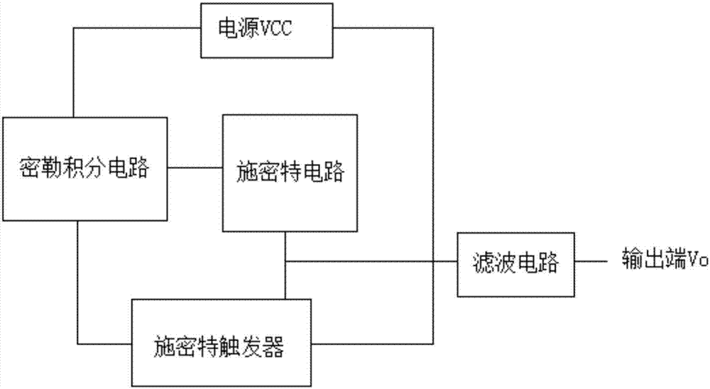
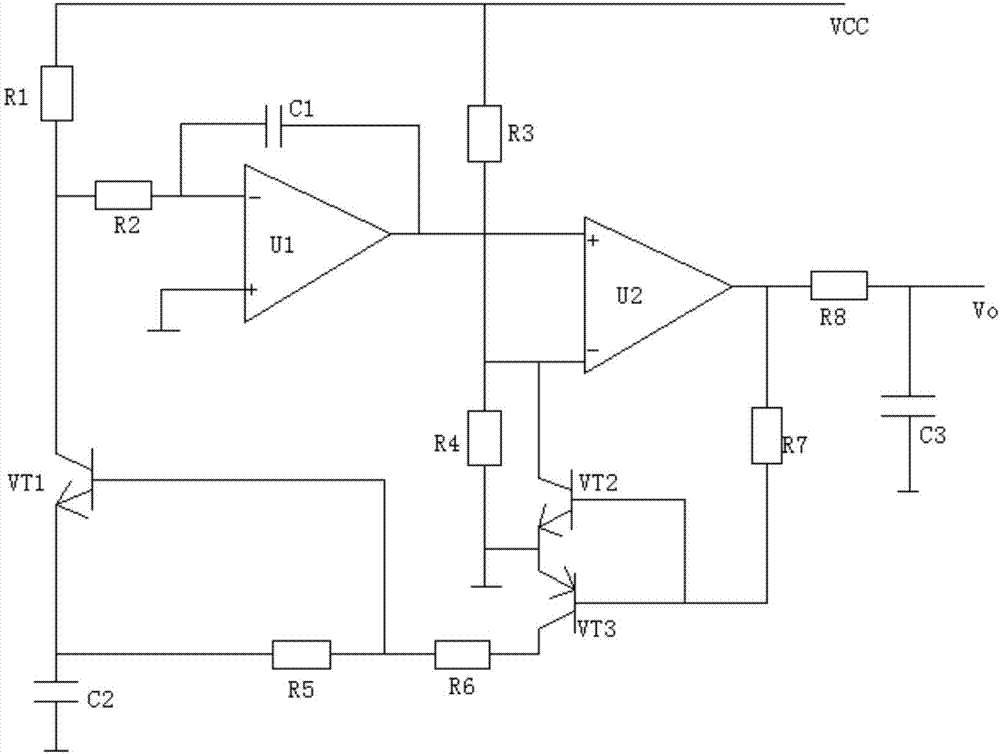
[0016] see Figure 1~2 , in an embodiment of the present invention, a waveform control system includes a Miller integrating circuit, a Schmitt circuit, a Schmitt trigger and a power supply VCC, the output end of the Miller integrating circuit is connected to the Schmitt circuit, and the output of the Schmitt circuit The terminals are respectively connected to the input terminal of the Schmitt trigger and the input terminal of the filter circuit, the output ter...


PUM


Abstract

The invention discloses a waveform control system, comprising a Miller integrating circuit, a Schmidt circuit, a Schmidt trigger and a power supply VCC, wherein the output end of the Miller integrating circuit is connected with the Schmidt circuit, the output end of the Schmidt circuit is separately connected with the input end of the Schmidt trigger and the input end of a filter circuit, the output end of the Schmidt trigger is connected with the input end of the Miller integrating circuit, the power supply VCC separately supplies power to the Miller integrating circuit and the Schmidt trigger, and the output end of the filter circuit is connected with the output end Vo of the system. According to the waveform control system disclosed by the invention, a direct current power supply VCC is directly converted to a square wave signal, the amplitude value and frequency of the square wave signal at the output end can be changed by changing the size of the power supply VCC and the charge and discharge frequency of a capacitor C1, the secondary amplification is not required, high stability can be achieved, and the obtained waveform is low in distortion rate.

Description

technical field [0001] The invention relates to a control system, in particular to a waveform control system. Background technique [0002] In analog electronic circuits, signals of various waveforms are often required, such as sine wave, rectangular wave, triangle wave and sawtooth wave, etc., as test signals or control signals, etc. The laboratory often converts these waveform signals to obtain other waveforms. However, the existing sine-to-square wave waveform conversion circuit has a narrow range of input signals, and the amplitude of the output square wave signal is uncontrollable, which is inconvenient to use. It is necessary to re-amplify the output square wave signal, which can easily lead to Signal distortion. Contents of the invention [0003] The purpose of the present invention is to provide a waveform control system to solve the problems raised in the background art above. [0004] To achieve the above object, the present invention provides the following tec...

Claims


Application Information

Patent Timeline
Patent Type & Authority Applications(China)
IPC IPC(8): H03K5/13
CPCH03K5/13
Inventor 王陈伟
Owner 王陈伟
Learn More