
base structure

A technology of bases and connecting parts, which is applied in the construction of electrical equipment components, cooling/ventilation/heating transformation, electrical components, etc., can solve the problems of internal temperature imbalance in the system, regional temperature cannot be cooled, etc., to avoid temperature fluctuations balanced effect

Inactive Publication Date: 2020-11-27
QISDA SUZHOU +1
View PDF7 Cites 0 Cited by
  • Summary
  • Abstract
  • Description
  • Claims
  • Application Information

AI Technical Summary

Problems solved by technology

However, the temperature in the dead zone of the flow field cannot be cooled, which may easily cause the problem of temperature imbalance inside the system

Method used


Image

  • base structure
  • base structure
  • base structure

Examples


Embodiment Construction

[0022] In order to have a further understanding of the purpose, structure, features and functions of the present invention, the detailed description is as follows in conjunction with the embodiments.

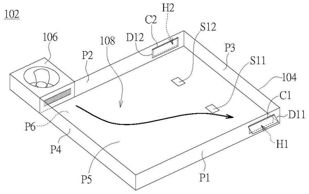
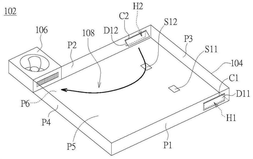
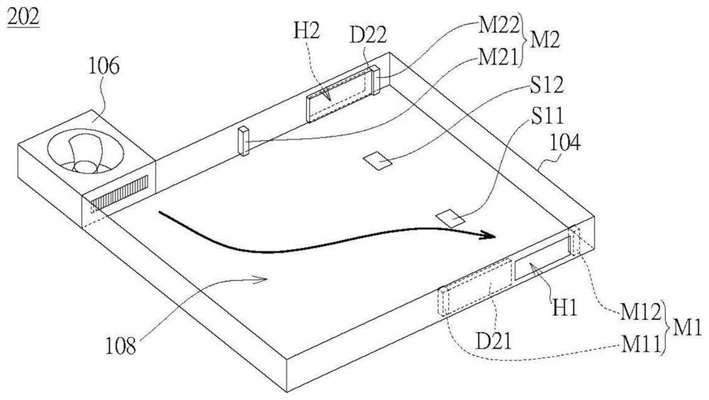
[0023] Please refer to figure 1 and figure 2 , which shows the base structure 102 and its operation method according to the first embodiment. The base structure 102 includes a housing 104 , a first valve D11 , a second valve D12 , a first sensor S11 , a second sensor S12 and a fan 106 .

[0024] The casing 104 has an accommodating space 108 defined by a plurality of plates and communicated with at least a first vent H1 and a second vent H2 . For example in detail, the housing 104 may include a first plate P1 and a second plate P2 opposite to each other, and a third plate P3 and a third plate P3 opposite to the first plate P1 and the second plate P2. Four boards P4. The casing 104 further includes a fifth plate P5 and a sixth plate P6 on opposite sides of the first plate P1 ...


PUM


Abstract

The present invention provides a substrate structure. The substrate structure comprises a housing, a first valve, a second valve, a sensor and a fan. The housing has a first ventilation opening, a second ventilation opening and a holding space which are communicated. The first valve is configured to control switching of the first ventilation opening. The second valve is configured to control switching of the second ventilation opening. The sensor is arranged in the holding space. the fan is configured to generate air flow in the holding space. When air flow flows one of the first ventilation opening and the second ventilation opening, the other one of the first ventilation opening and the second ventilation opening is closed. The substrate structure can control the flow field direction of the holding space in the housing to effectively perform regional cooling and avoid the problem that the temperature in the system is unbalance caused by the blind angle of the flow field.

Description

technical field [0001] The present invention relates to a base structure, and in particular relates to a base structure capable of arbitrarily changing the direction of the airflow field. Background technique [0002] Existing electronic devices, such as set-top boxes (digital video conversion boxes, Set-top boxes), projectors, optical drives, computer hosts, biomedical testing devices, etc., have components that generate heat during operation. Therefore, these electronic devices must Equipped with a cooling fan to cool its interior. However, the temperature in the dead zone of the flow field cannot be cooled, which may easily cause the problem of temperature imbalance inside the system. [0003] Therefore, it is necessary to propose a novel base structure that has solved the above-mentioned problems. Contents of the invention [0004] The purpose of the present invention is to provide a base structure that can control the direction of the flow field in the storage space...

Claims


Application Information

Patent Timeline
Patent Type & Authority Patents(China)
IPC IPC(8): H05K7/20
CPCH05K7/20145H05K7/20172H05K7/20209
Inventor 陈东炜
Owner QISDA SUZHOU
Learn More