Reduced pressure distillation device and method for preparing N-methyl-2-chloroethyl pyrrolidine
A technology for producing and distilling chloroethylpyrrolidine, which is applied in vacuum distillation, distillation regulation/control, organic chemistry, etc., can solve problems such as low distillation efficiency and unfavorable steam, achieve high distillation efficiency, realize condensation, and increase speed Effect
- Summary
- Abstract
- Description
- Claims
- Application Information
AI Technical Summary
Problems solved by technology
Method used
Image
Examples
Embodiment 1
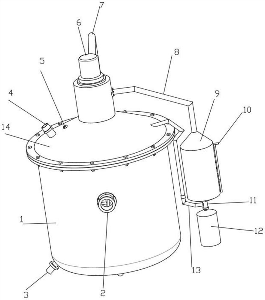
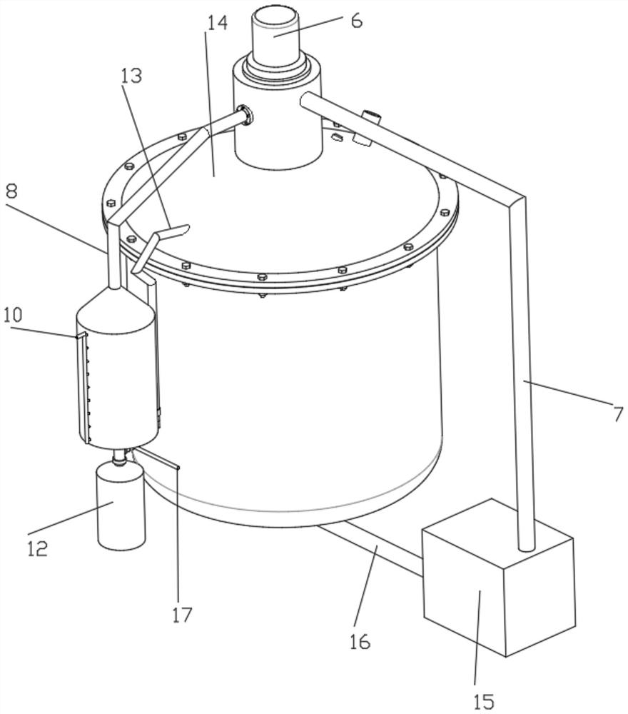
[0040] Such as figure 1 , 2, a kind of N-methyl-2-chloroethylpyrrolidine preparation shown in 3, 4, 5, 8, and 9 uses a vacuum distillation device, including a distillation tank 1, a sewage pipe 3, a feed pipe 4, and a collection tank 12 and a cover plate 14, the observation tube 2 is fixedly installed in the mounting hole at the upper end of the side wall of the retort 1, the bottom of the side wall of the retort 1 is fixedly connected with a blowdown pipe 3, the retort 1 is connected with a cover plate 14, and the cover plate 14 The side wall is fixedly connected with the feed pipe 4, and the side wall of the cover plate 14 is fixedly installed with a temperature sensor 5 for temperature monitoring. The top of the cover plate 14 is connected with a constant temperature stirring structure for constant temperature stirring of the solution. The constant temperature stirring structure includes a drive Motor 6, hot air inlet pipe 7, electric heater fan 15, hot air outlet pipe 16,...
Embodiment 2
[0043] Embodiment 2 is a further improvement to Embodiment 1.
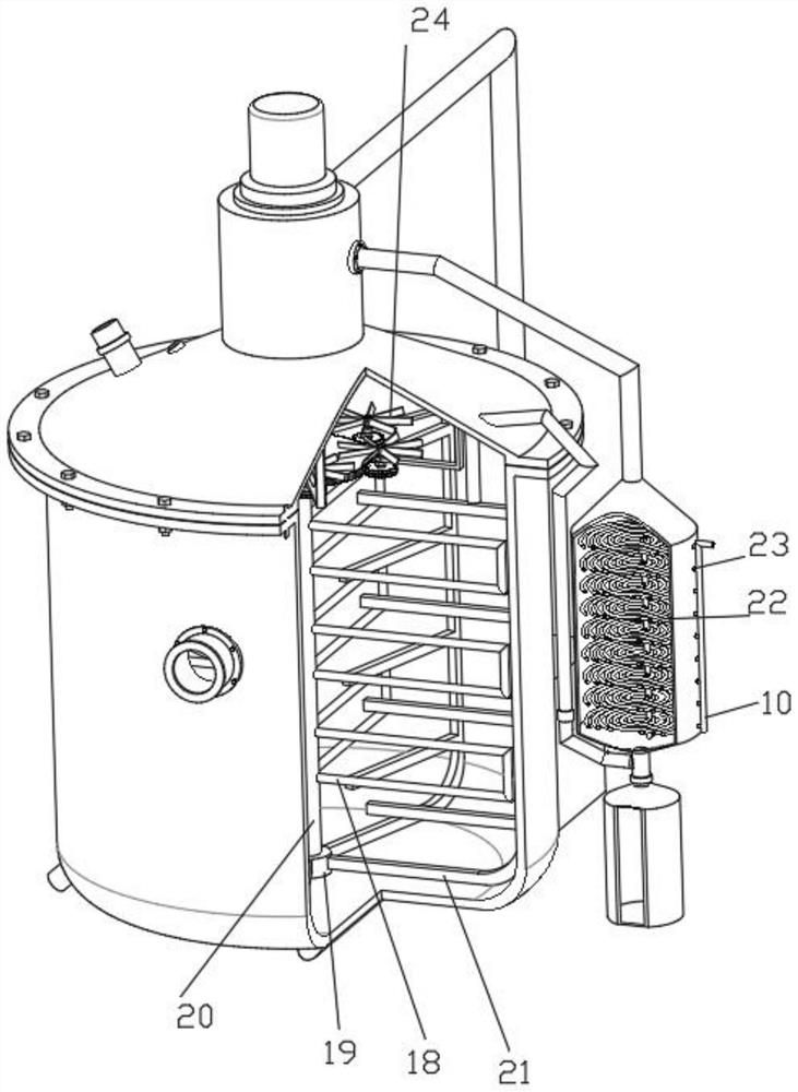
[0044] Such as image 3 , 4 , 7, the driving structure includes the fan blade 24, the first ring gear 25, the L-shaped mounting plate 26, the second ring gear 27 and the rotating shaft 31, the first ring gear 25 is fixedly installed on the outer wall of the hollow rotating shaft 20, the first tooth The ring 25 is evenly meshed with the second ring gear 27 along the circumferential direction, and the middle end straight hole of the second ring gear 27 is fixedly connected with the rotating shaft 31, and the top of the rotating shaft 31 is uniformly fixedly connected with the fan blade 24 along the circumferential direction. The lateral portion of the L-shaped mounting plate 26 is rotatably connected to the rotating shaft 31 through a fixedly connected bearing, and the L-shaped mounting plate 26 is fixedly mounted on the inner wall of the cover plate 14, and the hollow rotating shaft 20 drives the first ring gear 2...
Embodiment 3
[0046] Embodiment 3 is a further improvement to Embodiment 1.
[0047] Such as figure 1 , 3 , 4, 5, and 6, the cycle condensation structure includes steam outlet pipe 8, condensation pipe 9, cold water inlet pipe 10, straight pipe 11, steam inlet pipe 13, water outlet pipe 17, vortex capillary tube 22 and connecting pipe 23, steam The outlet pipe 8 is fixedly installed on the side wall of the cover plate 14, and the bottom of the outer end of the steam outlet pipe 8 is fixedly connected with a condensing pipe 9, and the side wall of the condensing pipe 9 is evenly and fixedly connected with a connecting pipe 23, and the outer end of the connecting pipe 23 is fixedly connected A cold water inlet pipe 10 is arranged, and the cold water inlet pipe 10 is connected with a cold water source. The inner end of the connecting pipe 23 is fixedly connected with a vortex capillary 22, and the inner end of the vortex capillary 22 is fixedly connected with the outer end of the water outlet...
PUM
| Property | Measurement | Unit |
|---|---|---|
| The inside diameter of | aaaaa | aaaaa |
| Thickness | aaaaa | aaaaa |
Abstract
Description
Claims
Application Information
 - R&D
- Intellectual Property
- Life Sciences
- Materials
- Tech Scout
- Unparalleled Data Quality
- Higher Quality Content
- 60% Fewer Hallucinations
Browse by: Latest US Patents, China's latest patents, Technical Efficacy Thesaurus, Application Domain, Technology Topic, Popular Technical Reports.
© 2025 PatSnap. All rights reserved.Legal|Privacy policy|Modern Slavery Act Transparency Statement|Sitemap|About US| Contact US: help@patsnap.com


